background image

TY-KJ16-001A 


                                                                                  ○


INSTRUCTION MANUAL 

FOR 

PRESSURE TRANSMITTER 

MODEL KJ16 


2017.6 

7.4

Summary of Contents for KJ16

Page 1: ...TY KJ16 001A エ INSTRUCTION MANUAL FOR PRESSURE TRANSMITTER MODEL KJ16 2017 6 7 4 ...

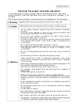
Page 2: ... fire or electrical shock Use this device within the operating temperature range Using outside the range of operating temperature may cause malfunction or damage of the product and result in injury or damage to surroundings Perform wire connection according to the wire connection faceplate or the wire connection instructions of the instruction manual Incorrect wire connection may cause injury or a...

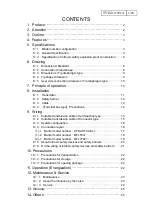
Page 3: ...l box type Precautions 12 9 Wiring 9 1 Suitable transmission cable of terminal box type 13 9 2 Suitable transmission cable of Connector type 15 9 3 System configuration 16 9 4 Connection layout 16 1 1 Barrier model number KFD2 STC4 Exl 17 1 2 Barrier model number MTL5541 18 2 1 Barrier model number MTL7787 19 9 5 About intrinsic safety devices and safety barriers 20 9 6 On the wiring of intrinsic ...

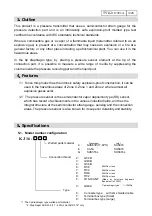
Page 4: ... exceeding 60 C of ambient temperature 1 Places which receive direct sunlight 1 Places exposed to liquid such as rainwater 2 Places of the atmosphere containing humidity salt sulfur etc 2 Places exposed to excessive load vibration or shock 3 Wiring which may damage the explosion proof of the intrinsically safe circuit 4 Maintenance inspection work for this product in a hazardous area 5 1 By receiv...

Page 5: ...safety explosion proof construction it can be used in the hazardous areas of Zone 0 Zone 1 and Zone 2 where almost all explosive gases exist 2 The pressure sensor is the semiconductor vapor deposition type SS sensor which has record of achievements in the various industrial fields and has the integral structure at the semiconductor strain gauge sensing and the connection areas The pressure sensor ...

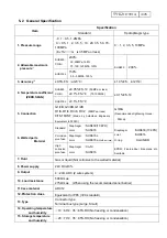
Page 6: ...A Recommended tightening torque 30N m 6 Wetted parts Material Standard Diaphragm Joint SUS630 17 4PH SUS316 Diaphragm Joint O ring SUS630 17 4PH SUS316 Hard NBR Corrosion proof use Diaphragm Joint SUS316L SUS316L 35 MPa or less High corrosion proof use Diaphragm Joint Co Ni SUS316 EPDM Fluororubber Neoprene etc Available 7 Fluid Gas or liquid Not corrosive to the wetted material 8 Power supply 24V...

Page 7: ...cy includes linearity hysteresis and repeatability 3 When using the recommended zener barrier MTL7787 please pay attention when using it as the load resistance that the user can connect is 275 Ω Including cable and other line resistance 16 Insulation resistance 100MΩ or more at 50V DC 17 Applicable Standard RoHS EU RoHS compliant EMC EN61326 1997 A1 1998 A2 2001 A3 2003 18 Weight Connector type Ap...

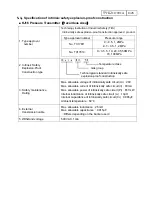
Page 8: ... type Exia ⅡC T4 Temperature class Gas group Technological standard intrinsically safe explosion proof construction 3 Safety maintenance Rating Max allowable voltage of intrinsically safe circuit Ui 28V Max allowable current of intrinsically safe circuit Ii 93mA Max allowable power of intrinsically safe circuit Pi 651mW Internal inductance of intrinsically safe circuit Li 10μH Internal capacitance...

Page 9: ...urrent of intrinsically safe circuit Io 86 8mA 93 0mA Max allowable power of intrinsically safe circuit Po 551mW 650mW Max allowable inductance of intrinsically safe circuit Lo 4 6mH 4 2mH Max allowable capacitance of intrinsically safe circuit Co 0 093μF 0 083μF Ambient temperature 60 60 6 Safe area load resistance intrinsically safe circuit 800ΩMAX at 20mADC 450ΩMAX at 20mADC Zener Type 1 Manufa...

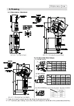
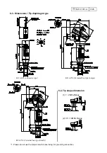
Page 10: ... case fixing for grounding connection 2 LC is printed by laser marking on one side of the joint hexagon for identification of the joint material SUS 316L 1 1 2 2 KJ16 2 KJ16 3 KJ16 4 G1 4B G3 8B G1 2B a 16 a 18 a 20 h 115 h 117 h 119 a 16 a 18 a 20 h 168 h 170 h 172 a 16 a 18 a 20 h 187 h 189 h 191 KJ16 7 KJ16 9 KJ16 6 KJ16 6 KJ16 7 KJ16 8 KJ16 9 R1 8 R1 4 R3 8 R1 2 b 14 b 16 b 18 b 20 h 110 h 112...

Page 11: ...diaphragm type KJ16 6V4 Connector type KJ16 9V4 Terminal box type Large KJ16 7V4 Terminal box type Small 1 Please do not use the side screws for case fixing for grounding connection 6 4 Tip shape dimension 1 1 2MPa Range 2 3 5 10MPa Range ...

Page 12: ...A DC through safety barrier placed in non hazardous area The diaphragm of a pressure receiver converts measured pressure into strain The amount of the strain is detected by semiconductor strain gauges which are vapor deposited on the diaphragm The detection circuit is full bridge type in which four sides of bridges are all constructed with semiconductor strain gauges By these bridge circuits elect...

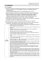
Page 13: ...pe threads please check for debris dirt and damage to the washer and seal face before installation to prevent leaks If there is a danger of surge pressure please concurrently use a damper and joint with throttle In case of the terminal box type please do not turn the ground up so as to prevent water from entering through the cable Always avoid pulling or severely bending cables Also during install...

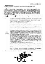
Page 14: ... one degree regardless of attaching direction Moreover in the case of using wireway water intrusion should be avoided as well Atmospheric pressure is introduced into the instrument by way of cable when the cable is pressed by a clamp or bushing or extreme bending in the middle of the cable or when the cable is long it takes time to exhaust pressure possibly causing output error due to the case int...

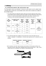
Page 15: ...ound Type Terminal box Terminal port size JIS F 8801 Gasket inner diameter mm Sheath outer diameter mm Core wire cross ectional area mm2 Withstand voltage AC V For 1 minute KJ16 7 Small G3 8 10a standard 7 6 7 0 25 1 65 500 Between conductor and ground 10b 8 7 8 KJ16 9 Large G1 2 15a 9 8 9 15b standard 10 9 10 15c 11 10 11 The allowable parameters specified for the external wiring of the intrinsic...

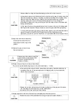
Page 16: ...one point so that there is no potential difference between them Open the lid of the terminal box and insert the cable from the terminal port all the way to the gasket Tighten the ground and close the terminal port Please connect the wire to the terminal block The recommended tightening torque to the terminal block is 1 2N m When using bare crimp terminal please take necessary insulation distance b...

Page 17: ...ble body is 4 wires there are green and blue wires other than red and white but green and blue wires are not used No internal connection Ambient temperature Core wire Cable outer diameter mm cross sectional area mm2 Constitution Number mm Shield cable standard 20 60 0 2 AWG25 7 0 18 φ6 2 Heat resistant cable 20 105 0 3 AWG23 12 0 18 φ6 0 Cold resistant cable 40 80 0 3 AWG23 12 0 18 φ6 0 Cable spec...

Page 18: ...please make one point ground so as not to generate a potential difference 2 Zener barrier 9 4 Connection layout 1 Isolated barrier As shown in the wiring diagrams on the following pages place the safety device KJ 16 in a hazardous place securely hold the equipment insulated barrier general equipment supply power receiver in a non hazardous place and connect In addition when purchasing an insulated...

Page 19: ...ping In the unlikely event that earth grounding from piping is impossible please use the shielded wire to ground the earth However when both the KJ16 main body and the shielded wire are grounded please make one point ground so as not to generate a potential difference Connecter Terminal box 1 A Red 1 3 C White 2 Earth E Shield 3 7 8 14 15 Terminal number of barrier Equipment Equipnement terminal P...

Page 20: ... piping In the unlikely event that earth grounding from piping is impossible please use the shielded wire to ground the earth However when both the KJ16 main body and the shielded wire are grounded please make one point ground so as not to generate a potential difference Connecter Terminal box 1 A White 2 2 C Red 1 Earth E Shield 3 11 12 13 14 Terminal number of barrier Equipment Equipnement termi...

Page 21: ... type barrier general equipment supply power receiver in a non hazardous place and connect When installing the safety cage a 35 mm wide DIN rail is required separately For connection details and other details please refer to the product instruction manual purchased 2 1 Recommended barrier Cooper Industries Japan K K wiring examples Barrier model number MTL7787 ...

Page 22: ...e device Combination conditions Safety maintenance rating of the safety barrier Max allowable voltage of intrinsically safe circuit Max allowable voltage of intrinsically safe circuit Max allowable current of intrinsically safe circuit Max allowable current of intrinsically safe circuit Max allowable electricity of intrinsically safe circuit Max allowable electricity of intrinsically safe circuit ...

Page 23: ...nd current which may damage the intrinsic safety explosion proof construction of the intrinsically safe circuit are not generated by electromagnetic or electrostatic induction Intrinsically safe wiring work etc should follow the Guide to Factory Explosion Proof Electrical Equipment for the Users Gas Explosion Proof 1994 published by the Technology Institution of Industrial Safety CAUTION ...

Page 24: ...acking and that the product format is in accordance with the order Should any abnormality be found please contact the purchasing agency or our sales office 11 Operation Energization Please check that there is no mistake in wiring again before turning on the power Furthermore please confirm that the rated voltage of the power supply the rated current the voltage input to the safety cage and the int...

Page 25: ...t please use a soft cloth containing water Do not use thinner benzene etc which may cause deterioration and failure 12 2 About the influence by the noise The problem of noise is complicated and there are many things that can not be easily solved theoretically and it is not perfect If the measured value fluctuates from time to time or shows a different value from the actual pressure the influence o...

Page 26: ...s from the control circuit wiring are effective 12 3 Service In the case of failure please contact your vendor or your local sales office after confirming disconnection of transmission cable power supply voltage etc Moreover please pack up the product concerned to prevent damage during transportation and include the written details of the failure ...

Page 27: ...throughout the usage natural disasters fire and other unavoidable events 4 Secondary damage caused by product defects that includes above items Despite of the customer awareness for the misuse or not the part that has apparent mark or traces such as deformation wear or burnt will be excluded form the warranty coverage and be charged for any necessary repair or exchange 14 Others This manual cannot...

Reviews: