background image


11 

TY-KJ55-002A Rev.3 


7. Wiring and Connection 

■ 

7.1 Transmission Cable (Applicable Transmission Cable) 

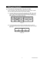
For the transmission cable used between KJ55 and the safety barrier, select a 
two-core shielded cable that satisfies the following conditions: 

(1)  The sheath diameter must suit the KJ55 cable gland (JIS F 8801 20f), and the 

core wire cross section must suit the internal terminal block. The cable must 
also be suitable for the withstand voltage between the cable conductors (core 
wires) and between the conductor and ground. 


(2)  The following values must be used for the allowable parameters (See "3.2 

Intrinsically Safe Specifications") defined as the external wire of the intrinsically 
safe circuit. 


Core wire 

count

Sheath 

diameter

Core wire 

cross 

Withstand voltage AC (V) 

1 minute

(Core)

mm

(mm

2

)

(Conductor - ground)

2

12 to 15

0.5 to 0.75

500

Allowable capacitance Allowable inductance

(Μf)

(mH)

0.015

2.5

<Table 7-1> 

<Table 7-2> 

Summary of Contents for KJ55 Series

Page 1: ...1 TY KJ55 002A Rev 3 User Manual for KJ55 Intrinsically Safe Pressure Transmitter 7 4 ...

Page 2: ...ns in this manual are categorized based on the following definition Indicates the risk that users may suffer from damage including death or serious injury and extremely high urgency at the time of occurrence of risk Indicates the risk that users may suffer from damage including death or serious injury Indicates the risk that users may suffer from minor injury and the risk that only property damage...

Page 3: ...environments listed below 1 Installation that degrades the explosive proof performance of the intrinsically safe circuit A place with an ambient temperature of above 60 C 1 A place exposed to direct sunlight 1 A place exposed to water such as rain 2 A place where atmosphere contains moisture salt or sulfur content 2 2 Wiring that degrades the explosive proof performance of the intrinsically safe c...

Page 4: ...condensation Otherwise the case erodes degrading the intrinsically safe protective performance or moisture in the air enters the case degrading the intrinsically safe insulating performance 3 For details see 7 Wiring and Connection 4 Only an appearance check is allowed in a hazardous area Be sure to perform other inspection checks in a non hazardous area Also avoid electrostatic charge To clean th...

Page 5: ...ortation 10 5 2 Precautions for Unpacking 10 6 Installation and Removal 10 6 1 Transmitter 10 6 2 Safety Barrier 10 6 3 Cable 10 7 Wiring and Connection 11 7 1 Transmission Cable Applicable Transmission Cable 11 7 2 Wiring Diagram 12 8 Operation Energization 14 9 Measures against Noise 14 9 1 Effects of Noise 14 10 Storage 15 10 1 Precautions for Storage 15 11 Maintenance 15 11 1 Inspection Output...

Page 6: ... explosive gas exist This product is so small in size and weight that it can be used easily Using a semiconductor evaporated type SS pressure sensor which has been applied in various industrial fields this product was integrally designed from the semiconductor strain gauge part to the sensing part and to the pressure connection part for higher durability and stability 2 2 Operating Principles This...

Page 7: ... Accuracy 1 0 5 F S 23 C Load resistance 500 Ω max Operating temperature humidity 20 to 60 C 35 to 85 RH non freezing non condensing Storage temperature humidity 30 to 80 C 35 to 85 RH non freezing non condensing Temperature coefficient 0 05 F S C zero point 0 05 F S C span Protection rating Equivalent to IP54 Case material ADC12 aluminum alloy Wetted materials Standard Diaphragm SUS630 17 4PH Fit...

Page 8: ...s Area The specifications of a recommended insulating barrier safety barrier paired with the KJ55 pressure transmitter are shown in the table below An insulating barrier does not need to be grounded as defined in the intrinsically safe standards because it is isolated from the intrinsically safe circuit A safety barrier can be selected by the user Table 3 2 Table 3 3 Exia II C T5 Temperature class...

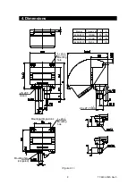
Page 9: ... Dimensions 2 x Ø 5 4 Model Thread size a b KJ55 83 G3 8B 18 133 KJ55 84 G1 2B 20 135 KJ55 85 Rc1 4 115 Figure 4 1 JIS 20F Gland Mounting hole 24 x 27 7 HEX Mounting hole Mounting dimensions Mounting hole elongated 2 x Ø 5 4 ...

Page 10: ...to use a spanner to tighten the hex parts of the threads for installation 5 Use a flexible pressure pipe when installing on a panel and perform wiring while preventing the instrument from being distorted 6 The product has superior vibration resistance However it must be installed in a place to avoid application of intense vibration because it is a precision instrument 6 2 Safety Barrier For detail...

Page 11: ...t the internal terminal block The cable must also be suitable for the withstand voltage between the cable conductors core wires and between the conductor and ground 2 The following values must be used for the allowable parameters See 3 2 Intrinsically Safe Specifications defined as the external wire of the intrinsically safe circuit Core wire count Sheath diameter Core wire cross Withstand voltage...

Page 12: ...am below If you purchase an insulating barrier Class A grounding defined in the intrinsically safe standards is not required For other wiring details see the user manuals of your purchased products Figure 7 1 2 Input Transmitter Hazardous Area Cable 2 Input 1 Input 11 Output 12 Output Receiving device GC95 Powersupplyfor receivingdevice Power supply 20 to 35V DC Barrier 14 Power Supply 13 Power Su...

Page 13: ...on Safety holding rating for safety barrier Allowable voltage of intrinsically safe circuit Maximum voltage of intrinsically safe circuit Allowable current of intrinsically safe circuit Maximum current of intrinsically safe circuit Allowable power of intrinsically safe circuit Maximum power of intrinsically safe circuit Hazardous area Non hazardous area Intrinsically safe equipment KJ55 Safety bar...

Page 14: ...herwise it may damage the safety barrier After powering on wait at least 5 minutes for warm up and start a production run 9 Measures against Noise 9 1 Effects of Noise If intermittent changes in measurement values or output are found or if pressure values different from actual ones are indicated they may be affected by noise Generally sources of noise include power supply an output cable periphera...

Page 15: ...s maintenance because the detection parts are not movable However it may change over time depending on usage conditions so it is recommended that you stop the operation and conduct periodical inspection about once every six months to make sure that there is no problem in each part Refer to the following check items of periodical inspection 1 Appearance check 2 Corrosion check of the pressure inlet...

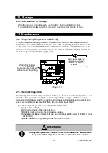
Page 16: ...cting span adjustment with the reference pressure gauge is described below 1 Adjust the output to 4 mA with the minimum range pressure 2 Apply the maximum range pressure and use the span trimmer to adjust the output to 20 mA 3 Repeat steps 1 and 2 alternately to adjust the span 4 The zero and span trimmers are located as shown below 11 4 Service If a failure is suspected check any cable breakage o...

Page 17: ...orces beyond control Secondary damage is generated from incompatibility of the product including the above conditions Note that traces of deformation wear and burnout of parts are apparently found regardless of recognition of your incorrect handling the product is out of the warranty range and is repaired or replaced for pay 12 2 Export Administration Regulations To export the product check Foreig...

Page 18: ...tion described in this user manual Copying or reprinting without permission is prohibited For other questions contact our sales office nearest you or call the number below User Manual for KJ55 Intrinsically Safe Pressure Transmitter April 2019 Rev 3 Website http www naganokeiki co jp lng eng NAGANO KEIKI CO LTD Head office 1 30 4 Higashi magome Ota ku Tokyo 143 8544 Phone 81 3 3776 5328 Fax 81 3 3...

Reviews: