13
TY-KJ55-002A Rev.3
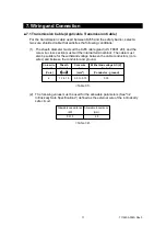
(1) System configuration diagram
(2)
Intrinsically safe equipment and safety barrier
The intrinsically safe equipment must be paired with the safety barrier to satisfy
the conditions in the two tables below so that the intrinsically safe performance
can be secured. Be sure to observe the following pairing conditions (See "3.2
Intrinsically Safe Specifications").
Pairing conditions for safety holding ratings
Safety holding rating for
intrinsically safe equipment
Pairing condition
Safety holding rating for
safety barrier
Allowable voltage of
intrinsically safe circuit
≥
Maximum voltage of
intrinsically safe circuit
Allowable current of
intrinsically safe circuit
≥
Maximum current of
intrinsically safe circuit
Allowable power of
intrinsically safe circuit
≥
Maximum power of
intrinsically safe circuit
Hazardous area
Non-hazardous
area
Intrinsically safe
equipment
(KJ55)
Safety barrier MTL5541 (insulating barrier)
Power supply
20 to 35 V
Receiving
device
+
-
(Ground)
+
-
+
-
+
-
+
-
+
-
2
1
14
13
12
11
E
Device
Terminal No.
of the barrier
Equipment terminal
1
POWER (-)
2
POWER (+)
Ground
GND
11
Output (-)
12
Output (+)
13
Power supply (-)
14
Power supply (+)
Power supply
KJ55
Receiving device
<Figure 7-2>
<Table 7-3>
<Table 7-4>


