6
TY-KJ55-002A Rev.3
1. Preface
Check the specifications of the delivered model.
An incorrect pressure range, power supply, or output causes accidents. Be sure to use the
model appropriate for specifications in the place suited for your operating environment,
and conduct secure wiring and installation.
2. Product Overview
This product is a pressure transmitter using a semiconductor strain gauge for the
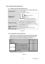
pressure detection part and was certified as intrinsically safe electrical equipment
by Nippon Kaiji Kyokai (ClassNK).
This intrinsically safe pressure transmitter was designed based on a concept of
maintaining the safety by restricting explosive energy from being supplied from a
safety barrier, installed between intrinsically safe equipment installed in a
hazardous area and non-intrinsically safe equipment installed in a non-hazardous
area, to the intrinsically safe equipment installed in the hazardous area.
■
2.1 Features
• With an intrinsically safe construction, this product can be used in Zone 0, 1, and 2
hazardous areas where almost all types of explosive gas exist.
• This product is so small in size and weight that it can be used easily.
• Using a
semiconductor evaporated type (SS) pressure sensor
, which has been
applied in various industrial fields, this product was integrally designed from the
semiconductor strain gauge part to the sensing part and to the pressure connection
part for higher durability and stability.
■
2.2 Operating Principles
This product is equipped with an intrinsically safe construction to measure and output
pressure of 4 to 20mA DC through a safety barrier installed in a non-hazardous area.
The product converts measured pressure into distortion with the diaphragm in the
pressure receiving part and detects the amount of distortion with the semiconductor
strain gauge deposited onto the diaphragm.
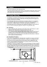
A detection circuit has a full-bridge system where all of four edges of a bridge consist of
semiconductor strain gauges. Electric signals in proportion to distortion can be obtained
from this bridge circuit. Then, the signals are transmitted as direct current output of 4 to
20mA DC through the amplifier circuit and output circuit in the next step (See the block
diagram below).
<Figure 2-1 Block diagram>
0 V
+24 V
R
ef
er
e
nc
e
pow
er
s
u
pp
ly
c
ir
c
ui
t
A
m
p
lif
ie
r
ci
rcu
it
Ou
tp
u
t
ci
rcu
it


