22
DT Series - Installation manual (V4_2022)
9.2.
EMERGENCY SHUTDOWN
When the heater shuts down in emergency, main electrical disconnect should be turned OFF,
and gas supply closed by shutting off the manual gas valve located in the supply gas line, out
of the unit.
9.3.
HEATER ON AFTER A FLAME FAILURE ALARM
After a flame failure alarm, perform the following checks:
BURNER
1. Ensure that all gas supply manual valves are opened;
2. Check status of the flame safeguard relay (For problems, refer to troubleshooting
section);
3. Check pilot flame rod and spark igniter;
4. Place main electrical disconnect to ON position;
5. Press the reset button of the flame safeguard relay;
6. Ensure that the blower motor is operating;
7. Ensure that the pilot ignites properly;
8. Fix all problems and repeat the start-up procedure.
10.
FLUE VENT & COMBUSTION AIR INTAKE
Depending on the model, the flue vent connector diameter ranges from 6 to 14 inches. The
heater is designed to operate effectively and safely (against a positive pressure of 0.25 in.w.c)
with a
positive stack (category IV) type
corrosion resistant single wall or double wall sealed flue
vent
listed
for this application, with minimum continuous temperature of at least
550°F
,
whether it is for vertical arrangement, horizontal arrangement, or a combination of both.
The minimum diameter of all sections must be identical to the connection diameter found on
the heater or greater.
Do not mix different listed vent system parts from different
manufacturers in the same venting system. Do not connect vent pipe in a common manifold
with another device. It is required that each heater be vented individually.
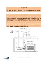
A listed vent cap or termination with (at least) the same diameter as the exhaust pipe of the
heater must be used at the end of the ducting located outside of the building. See figures 4-5-6
on page 25-26 showing the recommended end cap and configurations.
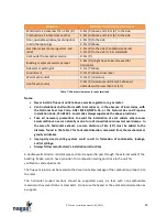
The exhaust pipe must end outside of the building and comply (at least but not limited to) the
following clearances:


