SCHEDULE TYPE:
PROJECT:
ENGINEER:
CONTRACTOR:
Nailor Industries Inc. reserves the right to change any information concerning product or pricing without notice.
DATE
B SERIES
SUPERSEDES DRAWING NO.
6 - 17 - 20
3000
4 - 30 - 20
P30RE-1
Page 1 of 2.
Dimensions are in inches (mm).
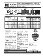
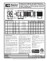
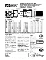
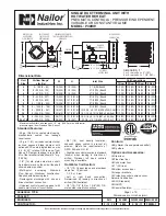
SINGLE DUCT TERMINAL UNIT WITH
ELECTRIC REHEAT
PNEUMATIC CONTROLS • PRESSURE INDEPENDENT
MODEL: P30RE
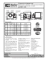
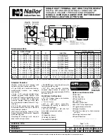
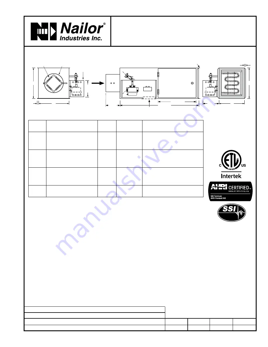
5 1/2"
(140)
15" (381)
31" (787)
W
5 3/4"
(146)
H
ELECTRIC COIL
CONT ROLS ENCLOSURE
(HINGED ACCESS DOOR)
1/2" (13)
W
1/2"
(13)
H
DAMPER
DRIVESHAFT
6 1/2"
(165)
INLET: ROUND,
FLAT OVAL OR
RECTANGULAR
UNIVERSAL PNEUMATIC
CONTROL MOUNTING
PANEL AND
PROTECTIVE
SHROUD
MULTI-POINT
AVERAGING
FLOW SENSOR
OPTIONAL
ACCESS DOOR
SLIP AND DRIVE
CONNECTION
AIRFLOW
Standard Features:
• 22 ga. (0.86) zinc coated steel casing,
mechanically sealed, low leakage
construction.
• 16 ga. (1.61) corrosion-resistant steel
inclined opposed blade damper with
extruded PVC seals (single blade on size
4, 5, 6). 45
°
rotation, CW to close. Tight
close-off. Damper leakage is less than
2% of the terminal rated airflow at 3" w.g.
(750 Pa).
• 1/2" (13) dia. plated steel drive shaft.
An indicator mark on the end of the shaft
shows damper position.
•
Multi-point averaging Diamond
Flow Sensor. Aluminum construction.
Supplied with balancing tees.
• Rectangular discharge with slip and
drive cleat duct connection.
• Universal control mounting panel with
double wall stand-off construction.
• 3/4" (19), dual density insulation,
exposed edges coated to prevent air
erosion. Meets the requirements of
NFPA 90A and UL 181.
• Electric Coil is mounted in an integral
attenuator section.
• Right-hand controls location is standard
(shown) when looking in direction of
airflow. Optional left hand controls
mounting is available.
Controls:
q
By Nailor. (See separate submittal).
q
By others.
Unit Options and
Accessories:
q
Steri-liner.
q
Fiber-free liner.
q
Solid metal liner.
q
1" (25) liner.
q
Bottom access door.
q
Hanger brackets.
q
Protective controls shroud cover.
q
20 ga. (1.00) construction.
Seismic Certification:
q
SSI (Standard).
q
OSHPD.
q
Special Features: ______________ .
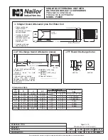
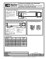
Electric Coil Features, Options and
Accessories:
See page 2 of 2.
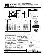
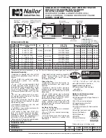
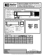
Dimensional Data
Unit
Size
Min.– Max. Airflow Range*
cfm (I/s)
W
H
Inlet
Size
4
30 – 180 (14 – 85)
10 (254)
10 (254)
3 7/8 (98) Round
5
55 – 325 (26 – 153)
10 (254)
10 (254)
4 7/8 (124) Round
6
80 – 450 (38 – 212)
10 (254)
10 (254)
5 7/8 (149) Round
7
115 – 650 (54 – 307)
12 (305)
12 1/2 (318)
6 7/8 (175) Round
8
155 – 900 (73 – 425)
12 (305)
12 1/2 (318)
7 7/8 (200) Round
9
200 – 1150 (94 – 543)
14 (356)
12 1/2 (318)
8 7/8 (225) Round
10
260 – 1500 (123 – 708)
14 (356)
12 1/2 (318)
9 7/8 (251) Round
12
355 – 2050 (168 – 967)
18 (457)
12 1/2 (318)
12 15/16 x 9 13/16 (329 x 249) Oval
14
440 – 2550 (208 – 1203)
24 (610)
12 1/2 (318)
16 1/16 x 9 13/16 (408 x 249) Oval
16
525 – 3040 (248 – 1435)
28 (711)
12 1/2 (318)
19 3/16 x 9 13/16 (487 x 249) Oval
24 x 16
1180 – 6800 (557 – 3209)
38 (965)
18 (457)
23 7/8 x 15 7/8 (606 x 403) Rect.
*
Minimum flows are based
upon 0.03" w.g. differential
pressure from flow sensor.
The maximum flow rate
represents the diamond flow
sensor's differential pressure
reading at 1" w.g. (250 Pa).
Listed


