A26
SINGLE DUCT TERMINAL UNITS
A
SINGLE DUCT TERMINAL UNITS • 3000Q SERIES
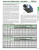
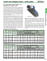
Recommended Airflow Ranges For
Single Duct Terminal Units
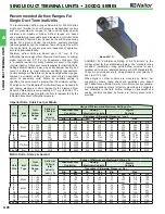
The recommended airflow ranges below are for 3000Q Series
single duct terminal units with pressure independent controls
and are presented as ranges for total and controller specific
minimum and maximum airflow. Airflow ranges are based
upon maintaining reasonable sound levels and controller limits
using Nailor's Diamond Flow Sensor as the airflow measuring
device. For a given unit size, the minimum, auxiliary minimum
(where applicable) and the maximum flow setting must be within
the range limits to ensure pressure independent operation,
accuracy and repeatability.
Minimum airflow limits are based upon .02" w.g. (5 Pa)
differential pressure signal from Diamond Flow Sensor on analog/
digital controls and .03" (7.5) for pneumatic controllers. This
is a realistic low limit for many transducers used in the digital
controls industry. Check your controls supplier for minimum limits.
Setting airflow minimums lower, may cause damper hunting and
result in a failure to meet minimum ventilation requirements.
Factory settings will therefore not be made outside these ranges;
however, a minimum setting of zero (shut-off) is an available
option on pneumatic units. Where an auxiliary setting is
specified, the value must be greater than the minimum setting.
The high end of the tabulated Total Airflow Range on pneumatic
and analog electronic controls represents the Diamond Flow
Sensor's differential pressure reading at 1" w.g. (250 Pa). The
high end airflow range for digital controls is represented by the
indicated transducer differential pressure.
ASHRAE 130 "Performance Rating of Air Terminals" is the
method of test for the certification program. The "standard rating
condition" (certification rating point) airflow volumes for each
terminal unit size are tabulated below per AHRI Standard 880.
These air volumes equate to an approximate inlet velocity of
2000 fpm (10.2 m/s).
When digital or other controls are mounted by Nailor, but
supplied by others, these values are guidelines only, based
upon experience with the majority of controls currently available.
Controls supplied by others for factory mounting are configured
and calibrated in the field. Airflow settings on pneumatic and
analog controls supplied by Nailor are factory preset when
provided.
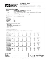
Model 3001Q
Imperial Units, Cubic Feet per Minute
Metric Units, Liters per Second
Unit
Size
Inlet
Type
Total
Airflow
Range,
cfm
Airflow at
2000 fpm
Inlet
Velocity
(nom.), cfm
Range of Minimum and Maximum Settings, cfm
Pneumatic 3000
Controller
Analog
Electronic Controls
Digital
Controls
Transducer Differential Pressure ( "w.g.)
Min.
Max.
Min.
Max.
Min.
Max.
.03
1.0
.02
1.0
.02
1.0
1.25
1.5
4
Round
0 – 225
150
30
180
25
180
25
180
200
225
5
0 – 400
250
55
325
45
325
45
325
360
400
6
0 – 550
400
80
450
65
450
65
450
500
550
7
Round
0 – 800
550
115
650
95
650
95
650
725
800
8
0 – 1100
700
155
900
125
900
125
900
1000
1100
9
0 – 1400
900
200
1150
165
1150
165
1150
1285
1400
10
0 – 1840
1100
260
1500
215
1500
215
1500
1675
1840
12
Flat Oval
0 – 2500
1600
355
2050
290
2050
290
2050
2300
2500
14
0 – 3125
2100
440
2550
360
2550
360
2550
2850
3125
16
0 – 3725
2800
525
3040
430
3040
430
3040
3400
3725
24 x 16
Rect.
0 – 8330
5350
1180
6800
960
6800
960
6800
7600
8330
Unit
Size
Inlet
Type
Total
Airflow
Range,
l/s
Airflow at
10.2 m/s
Inlet
Velocity
(nom.), l/s
Range of Minimum and Maximum Settings, l/s
Pneumatic 3000
Controller
Analog
Electronic Controls
Digital
Controls
Transducer Differential Pressure ( Pa )
Min.
Max.
Min.
Max.
Min.
Max.
7.5
249
5
249
5
249
311
374
4
0 – 106
71
14
85
12
85
12
85
94
106
5
Round
0 – 189
118
26
153
21
153
21
153
170
189
6
0 – 260
189
38
212
31
212
31
212
236
260
7
Round
0 – 378
260
54
307
45
307
45
307
342
378
8
0 – 519
330
73
425
59
425
59
425
472
519
9
0 – 661
425
94
543
78
543
78
543
606
661
10
0 – 868
519
123
708
101
708
101
708
790
868
12
0 – 1180
755
168
967
137
967
137
967
1085
1180
14
Flat Oval
0 – 1475
991
208
1203
170
1203
170
1203
1345
1475
16
0 – 1758
1321
248
1435
203
1435
203
1435
1604
1758
24 x 16
Rect.
0 – 3931
2525
557
3209
453
3209
453
3209
3586
3931

