FP0 Hardware
Self-Diagnostic and Troubleshooting
11-10
Matsushita Electric Works (Europe) AG
11.3 Error Codes
11.3.1
Total-Check Function
When the ERROR/ALARM LED on the FP0 control unit is blinking, a self
-
diagnostic
error or syntax check error has occured. Verify the contents of the error and take the
appropriate steps.
Procedure:
Error confirmation
1.
Use the programming tool to call up the error code
2.
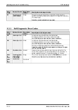
Check the error contents in the error code list of section
11.3.2 and 11.3.3 using the error code ascertained above.
11.3.1.1
Syntax Check Error
This is an error detected by the total
-
check function when there is a syntax error or
incorrect setting written in the program. When the mode switch of control unit is switched
to the RUN mode, the total
-
check function automatically activates and eliminates the
possibility of incorrect operation from syntax check errors in the program.
When a syntax check error is detected
ERROR/ALARM LED begins blinking.
Operation will not begin even after switching to the RUN mode.
Remote operation cannot be used to change to RUN mode.
Clearing a syntax error
By changing to the PROG. mode, the error will clear and the ERROR/ALARM LED will
turn OFF.
Steps to take for syntax error
Change to PROG. mode, and then execute the total-check function
while on-line with the programming tool connected. This will call up
the error contents and the address at which the error occurred.
Correct the program while referring to the error contents.
11.3.1.2
Self-Diagnostic Error
This error occurs when the contoller’s self-diagnostic function detects the occurence of
an abnormality in the system. The self-diagnostic function monitors the memory
abnormal detection, I/O abnormal detection, and other devices.
When the self-diagnostic error occurs
ERROR/ALARM LED begins blinking.
Summary of Contents for FP Series
Page 12: ...Chapter 1 Overview...
Page 21: ...FP0 Hardware Overview 1 10 Matsushita Electric Works Europe AG...
Page 22: ...Chapter 2 Control Units...
Page 44: ...Chapter 3 Expansion I O Units...
Page 67: ...FP0 Hardware Expansion I O Units 3 24 Matsushita Electric Works Europe AG...
Page 68: ...Chapter 4 Analog I O Unit...
Page 87: ...FP0 Hardware Analog I O Unit 4 20 Matsushita Electric Works Europe AG...
Page 88: ...Chapter 5 FP0 I O Link Unit MEWNET F...
Page 102: ...Chapter 6 Power Supply Unit...
Page 105: ...FP0 Hardware Power Supply Unit 6 4 Matsushita Electric Works Europe AG...
Page 106: ...Chapter 7 I O Allocation...
Page 112: ...Chapter 8 Installation...
Page 122: ...Chapter 9 Wiring...
Page 139: ...FP0 Hardware Wiring 9 18 Matsushita Electric Works Europe AG...
Page 140: ...Chapter 10 Trial Operation...
Page 143: ...FP0 Hardware Trial Operation 10 4 Matsushita Electric Works Europe AG...
Page 144: ...Chapter 11 Self Diagnostic and Troubleshooting...
Page 156: ...Appendix A System Registers...
Page 170: ...Appendix B Special Internal Relays...
Page 174: ...Appendix C Special Data Registers...
Page 183: ...FP0 Hardware Special Data Registers C 10 Matsushita Electric Works Europe AG...
Page 184: ...Appendix D Dimensions...
Page 195: ...FP0 Hardware Dimensions D 12 Matsushita Electric Works Europe AG...


