FP0 Hardware
11.3 Error Codes
11-11
Matsushita Electric Works (Europe) AG
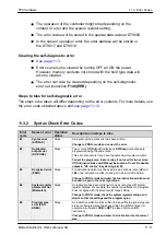
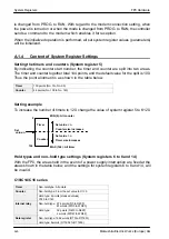
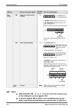
The operation of the controller might stop depending on the
content of error and the system resistor setting.
The error codes will be stored in the special data resister DT9000.
In the case of operation error, the error address will be stored in
the DT9017 and DT9018.
Clearing the self-diagnostic error
Errors can also be cleared by turning OFF an ON the power.
However, memory contents not stored with the hold type data will
also be cleared.
The error can also be cleared depending on the self-diagnostic
error set instruction F148(ERR).
Steps to take for self-diagnostic error
The steps to be taken will differ depending on the error contents. For more details, use
the error code obtained above and
11.3.2
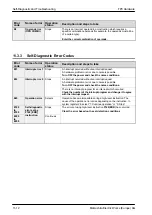
Syntax Check Error Codes
Error
code
Name of error
Operation
status
Description and steps to take
E1
Syntax error
Stops
A program with a syntax error has been written.
(SYNTAX)
Change to PROG. mode and correct the error.
E2
Duplicated
output error
(DUP USE)
Stops
Two or more OT(Out) instructions and KP(Keep) instructions are
programmed using the same relay.
This error also occurs if you have the same timer/counter numbers.
Correct the program so that one relay is not used for two or more
OT(Out) instructions and KP(Keep) instructions. Or, set the double
output to “K1: enable” in system register 20.
E3
Not paired error
(PAIR)
Stops
For instructions which must be used in a pair such as jump (JP and
LBL), one instruction is either missing or in an incorrect position.
Change to PROG. mode and enter the two instructions which must
be used in a pair in the correct positions.
E4
System register
parameter error
(Mismatch)
Stops
An instruction has been written which does not agree with system
register settings. For example, the number specification in a program
does not agree with the timer/counter range setting.
Change to PROG. mode, check the system register settings, and
adjust so that the settings and the program agree.
E5
Program area
error (PRG
AREA)
Stops
An instruction which must be written to a specific area (main program
area or subprogram area) has been written to a different area (for
example, a subroutine SUB to RET is placed before an ED
instruction).
Change to PROG. mode and enter the instruction into the correct
area.
Summary of Contents for FP Series
Page 12: ...Chapter 1 Overview...
Page 21: ...FP0 Hardware Overview 1 10 Matsushita Electric Works Europe AG...
Page 22: ...Chapter 2 Control Units...
Page 44: ...Chapter 3 Expansion I O Units...
Page 67: ...FP0 Hardware Expansion I O Units 3 24 Matsushita Electric Works Europe AG...
Page 68: ...Chapter 4 Analog I O Unit...
Page 87: ...FP0 Hardware Analog I O Unit 4 20 Matsushita Electric Works Europe AG...
Page 88: ...Chapter 5 FP0 I O Link Unit MEWNET F...
Page 102: ...Chapter 6 Power Supply Unit...
Page 105: ...FP0 Hardware Power Supply Unit 6 4 Matsushita Electric Works Europe AG...
Page 106: ...Chapter 7 I O Allocation...
Page 112: ...Chapter 8 Installation...
Page 122: ...Chapter 9 Wiring...
Page 139: ...FP0 Hardware Wiring 9 18 Matsushita Electric Works Europe AG...
Page 140: ...Chapter 10 Trial Operation...
Page 143: ...FP0 Hardware Trial Operation 10 4 Matsushita Electric Works Europe AG...
Page 144: ...Chapter 11 Self Diagnostic and Troubleshooting...
Page 156: ...Appendix A System Registers...
Page 170: ...Appendix B Special Internal Relays...
Page 174: ...Appendix C Special Data Registers...
Page 183: ...FP0 Hardware Special Data Registers C 10 Matsushita Electric Works Europe AG...
Page 184: ...Appendix D Dimensions...
Page 195: ...FP0 Hardware Dimensions D 12 Matsushita Electric Works Europe AG...

