FP0 Hardware
5.3
Specifications
5-5
Matsushita Electric Works (Europe) AG
5.3
Specifications
5.3.1
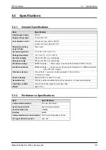
General Specifications
Item
Specification
Rated supply voltage
24V
DC
Supply voltage range
21.6 to 26.4V DC
Consumption current
I/O Link unit: max. 40mA / 24V DC
Control unit: max. 30mA / 24V DC
Allowed momentary
power off time
10ms (max)
Ambient temperature
0
_
C to 55
_
C (32
_
F to 131
_
F)
Storage temperature
–20
_
C to 70
_
C (–4
_
F to 158
_
F)
Ambient humidity
30% to 85% RH
(
non–condensing
)
Storage humidity
30% to 85% RH
(
non–condensing
)
Breakdown voltage
RS485 terminals
←→
Power supply / function earth terminals: AC500V 1minute
Insulation resistance
RS485 terminals
←
→
Power supply / function earth terminals: min. 100M
Ω
(measured
with a 500V DC megger)
Vibration resistance
10Hz to 55Hz, 1 cycle/min.: double amplitude 0.75mm (0.03in.),
10 minutes on 3 axes.
Shock resistance
Minimum 98m
/
s
2
, 4 times on 3 axes.
Noise immunity
1000Vp–p with pulse widths 50ns and 1
µ
s (based on in–house measurements)
Operating condition
Free from corrosive gases and excessive dust
Weight
Approx. 85g
5.3.2
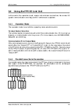
Performance Specifications
Item
Specifications
Communication method
Two–line, half–duplex
Synchronous method
Asynchronization system
Communication rate
0.5Mbps
Interface
RS485
Communication error check method
CRC (Cyclic Redundancy Check)
I/O map of FP0 I/O Link Unit
32X / 32Y
Summary of Contents for FP Series
Page 12: ...Chapter 1 Overview...
Page 21: ...FP0 Hardware Overview 1 10 Matsushita Electric Works Europe AG...
Page 22: ...Chapter 2 Control Units...
Page 44: ...Chapter 3 Expansion I O Units...
Page 67: ...FP0 Hardware Expansion I O Units 3 24 Matsushita Electric Works Europe AG...
Page 68: ...Chapter 4 Analog I O Unit...
Page 87: ...FP0 Hardware Analog I O Unit 4 20 Matsushita Electric Works Europe AG...
Page 88: ...Chapter 5 FP0 I O Link Unit MEWNET F...
Page 102: ...Chapter 6 Power Supply Unit...
Page 105: ...FP0 Hardware Power Supply Unit 6 4 Matsushita Electric Works Europe AG...
Page 106: ...Chapter 7 I O Allocation...
Page 112: ...Chapter 8 Installation...
Page 122: ...Chapter 9 Wiring...
Page 139: ...FP0 Hardware Wiring 9 18 Matsushita Electric Works Europe AG...
Page 140: ...Chapter 10 Trial Operation...
Page 143: ...FP0 Hardware Trial Operation 10 4 Matsushita Electric Works Europe AG...
Page 144: ...Chapter 11 Self Diagnostic and Troubleshooting...
Page 156: ...Appendix A System Registers...
Page 170: ...Appendix B Special Internal Relays...
Page 174: ...Appendix C Special Data Registers...
Page 183: ...FP0 Hardware Special Data Registers C 10 Matsushita Electric Works Europe AG...
Page 184: ...Appendix D Dimensions...
Page 195: ...FP0 Hardware Dimensions D 12 Matsushita Electric Works Europe AG...

