FP0 Hardware
4.1
Parts and Terminology
4-3
Matsushita Electric Works (Europe) AG
4.1.1
Analog Mode Switch Setting
Mode
Switch
number
Range
Analog
input
range
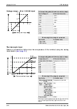
0 to 5V
0 to 20mA
–10 to +10V
K type thermo–
couple (
see notes
3, 4
)
J type thermo–
couple (
see notes
3, 4
)
T type thermo–
couple (
see notes
3, 4
)
switching 1 to 3, 5
No
averaging
(
see
note 1
)
With
averaging
(
see
note 2
)
No aver–
aging
(
see
note 1
)
With av–
eraging
(
see
note 2
)
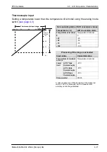
Temper–
ature of
terminal
to
1000
°
C
–100
°
C
to
temper–
ature of
terminal
Temper–
ature of
terminal
to 750
°
C
–100
°
C
to
temper–
ature of
terminal
Temper–
ature of
terminal
to 350
°
C
–100
°
C
to
temper–
ature of
terminal
1
2
3
ON
5
Analog
output
4
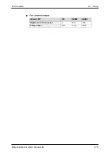
0 to
20mA
–10 to
+10V
range
switching
ON
4
Notes
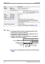
1) No averaging: Conversion data is set for the specified input
contact point area for each A/D conversion, on each channel.
2) With averaging: On each channel, for each A/D conversion,
the maximum and minimum values from the data of the last
ten times are excluded, and the data from the other eight times
is averaged, and the result set (
3) If a thermocouple setting is used, averaging is carried out,
regardless of the switch settings (
4) After turning on the analog unit, 20 minutes are required for
the transient state to reach a measurement accuracy of 99%.
During this time, deviations of
10
C can occur.
time
measurement
accuracy
20 min.
99%
10
C
Summary of Contents for FP Series
Page 12: ...Chapter 1 Overview...
Page 21: ...FP0 Hardware Overview 1 10 Matsushita Electric Works Europe AG...
Page 22: ...Chapter 2 Control Units...
Page 44: ...Chapter 3 Expansion I O Units...
Page 67: ...FP0 Hardware Expansion I O Units 3 24 Matsushita Electric Works Europe AG...
Page 68: ...Chapter 4 Analog I O Unit...
Page 87: ...FP0 Hardware Analog I O Unit 4 20 Matsushita Electric Works Europe AG...
Page 88: ...Chapter 5 FP0 I O Link Unit MEWNET F...
Page 102: ...Chapter 6 Power Supply Unit...
Page 105: ...FP0 Hardware Power Supply Unit 6 4 Matsushita Electric Works Europe AG...
Page 106: ...Chapter 7 I O Allocation...
Page 112: ...Chapter 8 Installation...
Page 122: ...Chapter 9 Wiring...
Page 139: ...FP0 Hardware Wiring 9 18 Matsushita Electric Works Europe AG...
Page 140: ...Chapter 10 Trial Operation...
Page 143: ...FP0 Hardware Trial Operation 10 4 Matsushita Electric Works Europe AG...
Page 144: ...Chapter 11 Self Diagnostic and Troubleshooting...
Page 156: ...Appendix A System Registers...
Page 170: ...Appendix B Special Internal Relays...
Page 174: ...Appendix C Special Data Registers...
Page 183: ...FP0 Hardware Special Data Registers C 10 Matsushita Electric Works Europe AG...
Page 184: ...Appendix D Dimensions...
Page 195: ...FP0 Hardware Dimensions D 12 Matsushita Electric Works Europe AG...

