23
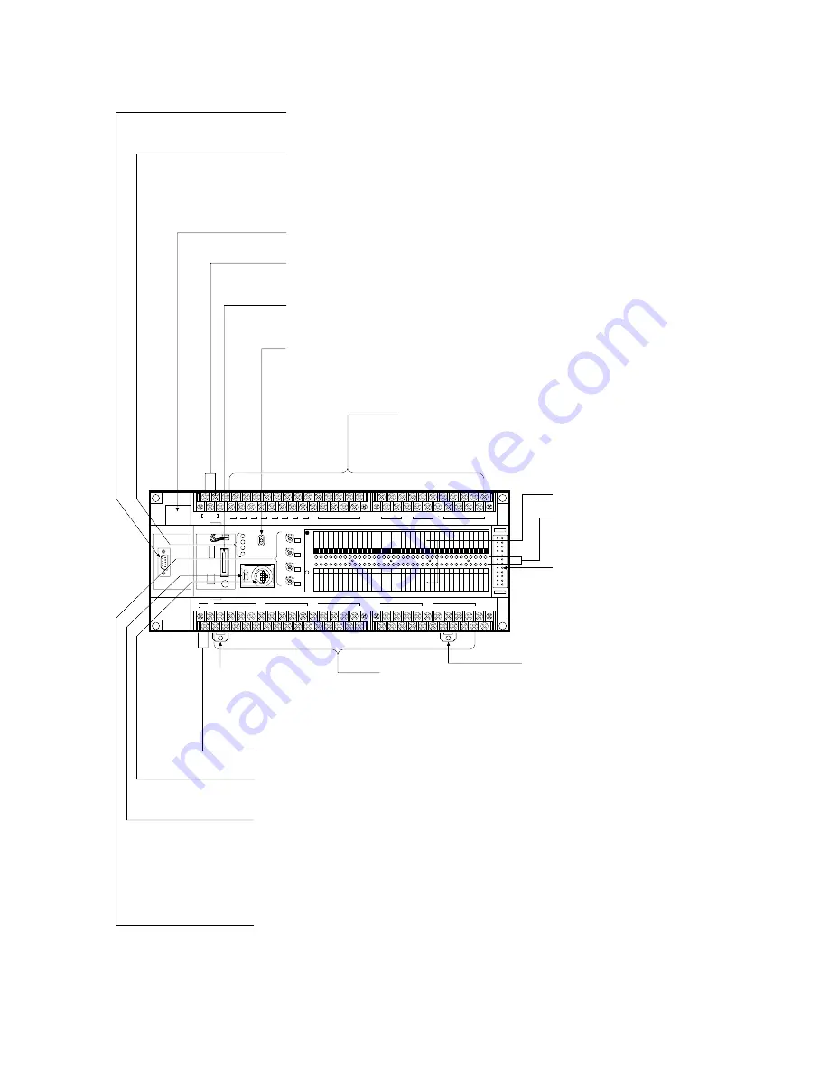
2-1. Parts Terminology and Functions
2) C24, C40, C56, and C72 Series (Illustration: C72 series, AC type)
0
RUN
REMOTE
PROG.
OUTPUT
INPUT
X
Y
(Relay)
(12-24V DC)
V0
max.
min.
RUN
PROG.
ERR.
ALARM
1
2
3
4
5
6
7
8
9 A B C D E F
0
1
2
3
4
5
6
7
8
9 A B C D E F
0
1
2
3
0
1
2
3
4
5
6
7
8
9 A B C D E F
0
1
2
3
4
5
6
7
8
9 A B C D E F
0
1
2
3
V1
max.
min.
V2
max.
min.
V3
max.
min.
BATTERY
COM
0
1
2
3
COM
4
5
6
7
COM
8
9
A
F
B
C
D
E
COM
8
9
A
F
B
C
D
E
COM
0
COM
1
COM
2
COM
3
COM
4
COM
5
COM
6
COM
7
L
N
100-240V AC
F.G.
COM
F
8
9
E
A
B
C
D
(+)
-
COM
7
0
1
6
2
3
4
5
(+)
-
COM
F
8
9
E
A
B
C
D
(+)
-
COM
7
0
1
6
2
3
4
5
(+)
-
COM
7
0
1
6
2
3
4
5
(+)
-
24V DC
+
-
FP1-002-93-B
RS232C Port (C24C, C40C, C56C, and C72C types only):
Use this connector to connect a peripheral device. [e.g., I.O.P.
(Intelligent Operating Panel), Bar-code reader and Serial printer, etc.]
Operation Monitor LEDs:
RUN LED
PROG. LED
ERR. LED
ALARM LED
Backup Battery Holder:
Refer to page 216, “7-3. Maintenance”, for details about backup battery replacement.
Power Supply Terminals:
• AC type Control Unit: power supply terminals for 100 V AC to 240 V AC
• DC type Control Unit: power supply terminals for 24 V DC
Connector for Memory (EPROM) and Master Memory (EEPROM):
Use this connector to connect the Memory (EPROM) and the Master Memory (EEPROM).
Mode Selector:
RUN mode:
REMOTE mode:
PROG. mode:
Output Terminals:
C24 series: 8 points, C40 series: 16 points, C56 series: 24 points,
C72 series: 32 points
This terminal block is removable with screws at both ends.
Terminals marked with “•” cannot be used as output terminals.
I/O Name Board
I/O State Indicators:
Indicates the input and output
ON/OFF states.
Expansion Connector:
Connects to the FP1 Expansion
Unit or FP1 Intelligent Unit
(FP1 A/D Converter Unit or FP1
D/A Converter Unit) or FP1 I/O
Link Unit.
See page 12 and 42.
DIN Rail Attachment Lever
Input Terminals:
C24 series: 16 points, C40 series: 24 points, C56 series: 32 points,
C72 series: 40 points
Input voltage range: 12V DC to 24 V DC
This terminal block is removable with screws at both ends.
Terminals marked with “•” cannot be used as input terminals.
Built-in DC Power Output Terminals for Inputs (AC type only):
DC power for inputs can be supplied from these terminals. See page 45.
Programming Tools Connector (RS422 port):
Use this connector to connect the programming tools (e.g., FP Programmer
II
or personal
computer with NPST-GR Software) using the FP1 Peripheral Cable.
Baud Rate Selector:
Selects the baud rate for communication with a peripheral device (FP Programmer,
FP Programmer
II
or personal computer with NPST-GR Software).
Sets the baud rate selector according to the peripheral device to be connected to the RS422 port.
FP Programmer (AFP1112):
FP Programmer (AFP1112A):
FP Programmer
II
(AFP1114):
Personal computer with NPST-GR:
Potentiometers (V0 to V3):
Set with a screwdriver, the potentiometers allow you to manually adjust the controller.
This feature lets you input an analog value ranging from 0 to 255.
Each set value is stored respectively in manual dial-set registers (V0: DT9040, V1: DT9041,
V2: DT9042 and V3: DT9043).
C24 series: 2 (V0 and V1); C40, C56, and C72 series: 4 (V0 to V3)
The Control Unit executes programs.
The mode (RUN mode or PROG. mode) can be changed using programming
tools (e.g., FP Programmer
II
and personal computer with NPST-GR Software).
You can edit a program.
when program is executed
when forcing input/output is executed in RUN mode
when the Control Unit halts program execution
when a self-diagnostic error occurs
when an abnormality is detected or watchdog timer error occurs
19,200 bps
19,200 bps or 9,600 bps
19,200 bps or 9,600 bps
9,600 bps
DIN Rail
Attachment Lever
ON:
Flashes:
ON:
ON:
ON:
2-1. Parts Terminology and Functions
Summary of Contents for FP1
Page 1: ...PROGRAMMABLE CONTROLLER FP1 is a global brand name of Matsushita Electric Works Hardware ...
Page 28: ...20 ...
Page 98: ...90 ...
Page 150: ...142 ...
Page 208: ...200 ...
Page 226: ...218 ...
Page 280: ...272 ...


