42
3-2. Expansion
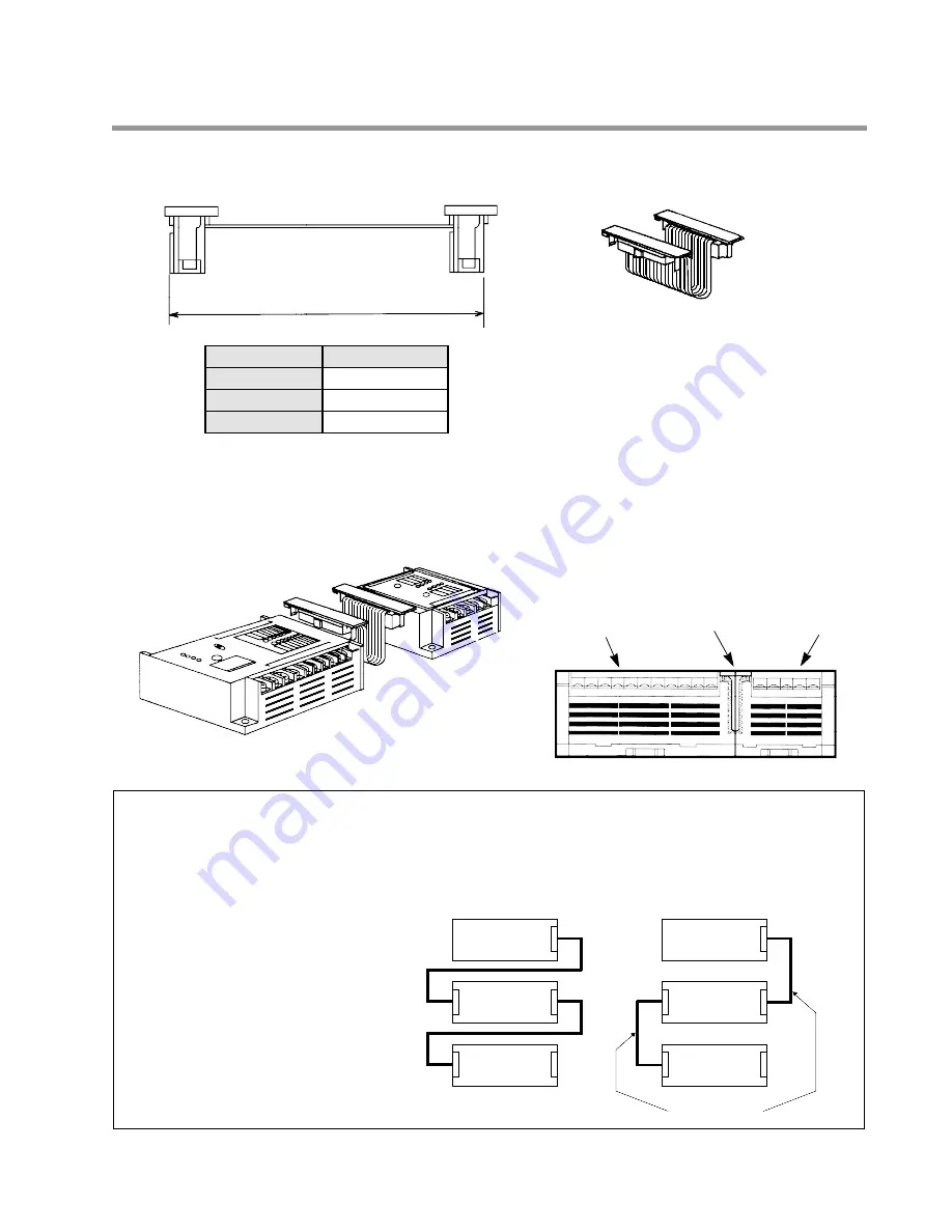
1. Expansion Cable
2. Unit Expansion
• Connect the Control Unit to the Expansion Unit, Intelligent unit (FP1 A/D Converter Unit, FP1 D/A Converter Unit)
or FP1 I/O Link Unit using Expansion Cable that folds out of sight and out of the way. In addition, concealing the
Expansion Cable helps avoid the potentially adverse effects of electrical noise.
Notes:
• A maximum of two Expansion Units, one FP1 A/D Converter Unit, two FP1 D/A Converter Units, and one
FP1 I/O Link Unit can be simultaneously connected to one Control Unit.
• There are no restrictions on the order in which units are connected.
• An E8 series and E16 series Expansion Unit cannot be connected in succession.
Refer to page 11, “1-3. Expansion and Configurations”, for details about combination of units.
Control Unit
Expansion Unit
Expansion Unit
Control Unit
Expansion Unit
Expansion Unit
Left
Left
Right
Right
Expansion
Cable
Expansion
Cable
Right
CORRECT
INCORRECT
Left
Left
Expansion
Cable
Right
Example:
Example:
• Units must be connected left to
right of each unit, therefore,
please use the Expansion Cable
(30 cm/0.984 ft.: AFP15103, 50
cm/1.640 ft.: AFP15105) when the
units are aligned as shown in the
right illustration.
Cable length
7 cm/0.230 ft.
30 cm/0.984 ft.
50 cm/1.640 ft.
Part number
AFP15101
AFP15103
AFP15105
3-2. Expansion
• The Expansion Cable can be concealed in
the between the units.
Control Unit
Example:
Expansion Unit
Cable length
Control Unit
Expansion Cable
Expansion Unit
Summary of Contents for FP1
Page 1: ...PROGRAMMABLE CONTROLLER FP1 is a global brand name of Matsushita Electric Works Hardware ...
Page 28: ...20 ...
Page 98: ...90 ...
Page 150: ...142 ...
Page 208: ...200 ...
Page 226: ...218 ...
Page 280: ...272 ...


