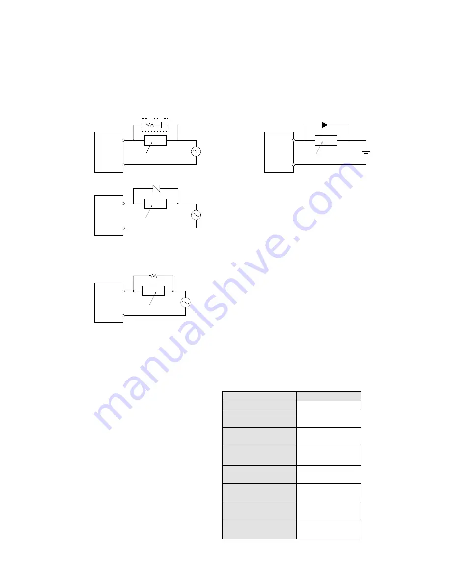
3) Output Wiring Examples
• Connect a protective circuit such as the one shown below when switching inductive loads.
When switching DC type inductive loads with a relay type output unit, be sure to connect a diode across the ends of
the load.
When using an AC inductive load
When using a DC inductive load
• When there is a low current load with the triac output type, the load may not go off because of the leakage current.
If this type of trouble should arise, connect a resistor in parallel with the load, as shown in the diagram below.
• There is no fuse in the output circuit. Please provide a fuse externally in order to protect the output circuit from
load shorts.
• Mounting the Protective Device
In the actual circuit, it is necessary to locate the protective device (diode, resistor, capacitor, varistor, etc.) in the
immediate vicinity of the load or contact. If located too far away, the effectiveness of the protective device may
diminish. As a guide, the distance should be within 50 cm (19.685 in.)
Resistive load
Solenoid load
Motor load
Incandescent lamp load
Mercury lamp load
Sodium vapor lamp load
Capacitive load
Transformer load
Steady state current
10 to 20 times the
steady state current
5 to 10 times the
steady state current
10 to 15 times the
steady state current
Approx. 3 times the
steady state current
1 to 3 times the
steady state current
20 to 40 times the
steady state current
5 to 15 times the
steady state current
Type of load
Inrush current
• Type of Load and Inrush Current
The type of load and its inrush current
characteristics, together with the
switching frequency are important
factors which cause contact welding.
Particularly for loads with inrush
currents, measure the steady state
current and inrush current and use a
relay or magnet switch which provides
an ample margin of safety. The table on
the right shows the relationship between
typical loads and their inrush currents.
COM
FP1
Output
terminal
Load
FP1-042-93-B
Resistor
COM
FP1
Output
terminal
Inductive load
FP1-041-93-B
Surge absorber
Example:
R
C
COM
FP1
Output
terminal
Inductive load
Diode
COM
FP1
Output
terminal
Inductive load
Varister
R: 50
Ω
C: 0.47
µ
F
50
3-3. Wiring
Summary of Contents for FP1
Page 1: ...PROGRAMMABLE CONTROLLER FP1 is a global brand name of Matsushita Electric Works Hardware ...
Page 28: ...20 ...
Page 98: ...90 ...
Page 150: ...142 ...
Page 208: ...200 ...
Page 226: ...218 ...
Page 280: ...272 ...


