
16
17
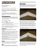
naishkites.com
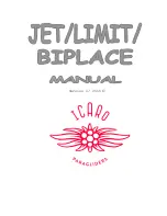
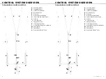
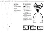
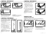
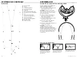
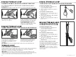
To increase bar width 5 cm: Pull the bar/line
adjuster out of the bar end as shown.
Reinstall the bar/line adjuster by pushing it back
into the bar end, while pulling the leader line above
the floater to remove any slack as shown.
IMPORTANT:
Repeat this procedure on the
opposite bar end so the bar width adjustment is
done exactly the same on both sides.
To decrease bar width 5 cm: Rotate the bar/line
adjuster 180 degrees as shown.
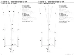
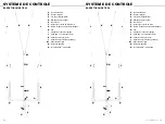
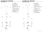
CONTROL SYSTEM BAR
CONTROL SYSTEM BAR
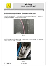
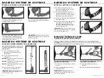
ADJUSTING TORQUE BAR WIDTH
1
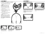
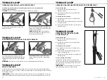
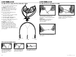
- Using a flying line, pull the bar/line
adjuster up as shown.
2
- The leader line knot holds the bar/line
adjuster in position, so you will need
to pull the leader line through the bar
end slightly to loosen the bar adjuster
for rotation.
3
- Rotate the bar/line adjuster 180 degrees.
4
- Reinstall the bar/line adjuster by pushing
it back into the bar end, while pulling
the leader line above the floater to
remove any slack.
IMPORTANT:
Repeat this procedure on
the opposite bar end so the bar width
adjustment is done exactly the same on
both sides.
CONTROL SYSTEM BAR
ADJUSTING THE BASE BAR WIDTH
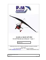
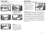
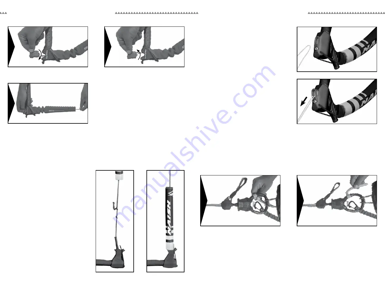
To connect the Torque Loop and Chicken Finger
to the harness hook:
1
- Hook the Torque Loop onto the harness hook.
2
- Insert the Chicken Finger into the center
section of the harness hook.
WARNING:
Make sure the Chicken Finger
is positioned below the Torque Loop and is
completely inserted into the harness hook.
To disconnect the Torque Loop and
Chicken Finger from the harness hook:
1
- Pull the Chicken Finger out of the harness hook.
2
- Unhook the Torque Loop from the harness hook.
The Chicken Finger is designed to hold the Torque Loop in position in the harness hook.
TORQUE LOOP
OPERATING THE CHICKEN FINGER
WARNING:
To release yourself from the kite in an emergency situation, you must activate the
Torque Loop Quick Release when the Chicken Finger is installed.
1
3
2
1
2
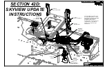
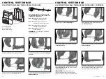
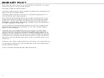
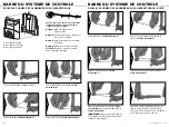
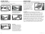
Repositioning the leader lines on the knots
under the floaters changes the length of the
steering (rear) flying lines.
1
- Pull the floaters up to expose the leader
line adjustment knots.
2
- Adjust the leader line to the desired
knot position.
Knot A:
Increases the length of the Steering
(Rear) Flying Lines (+5 cm).
Knot B:
Naish Control Systems are
delivered in the Knot B position.
Knot C:
Decreases the length of the
Steering (Rear) Flying Lines (-5 cm).
3
- Pull the floaters down to cover the leader
line adjustment knots.
IMPORTANT:
Repeat this procedure on the
opposite bar end so the leader line length
adjustment is done exactly the same on
both sides.
ADJUSTING BASE BAR STEERING (REAR) FLYING LINES
B
A
C