11
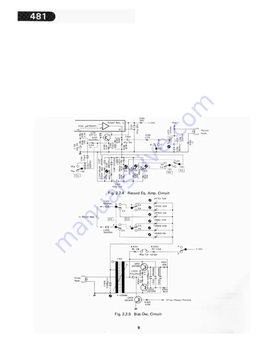
2.2.2. Record Equalizer Amplifier Circuit
The record equalizer amplifier circuit consists of the Out
put Amp. incorporated in the Dolby NR IC and peripheral
circuits as shown in Fig. 2.2.4.
VR1
0
2, VR1
0
3, and VR1
0
4 are the record calibration
semi-fixed volumes for ZX, SX and EX tapes. The output
of the Output Amp. is given to these volumes, and the
outputs from the volumes are fed back to the inverting
input of the Output Amp. via amplifier Q103 and a
time-constant changeover circuit.
By adjusting L104, compensation for the high frequency
range is made by setting a resonance frequency at 21
kHz or neighborhood.
L105, C138 and C139 compose a recording bias trap cir-
cuit.
2.2.3. Bias Oscillation Circuit
Fig. 2.2.5 shows a push-pull oscillator with an oscillation
frequency of 105 kHz which is constructed by capacitors
C302 and C3
0
3, coupling the collectors and bases of two
transistors (Q301 and Q302).
This is used to provide recording bias and as an erase sig
-nal.
By pressing the Record and Pause, or Record and Play
Buttons, (Play+ Pause)-position signal conducted from
the Logic P.C.B. Ass’y becomes H and Q3
0
3 turns to ON.
Therefore, +24 V is applied to the circuit, as a result of
which oscillation begins.
When the record mode is released, oscillator output is
damped by the discharge of C304. This prevents mag
-netization of the Record Head.
Summary of Contents for 481
Page 1: ......
Page 4: ......
Page 17: ......
Page 20: ......
Page 22: ......
Page 36: ...6 PARTS LOCATION FOR ELECTRICAL ADJUSTMENT ...
Page 37: ......
Page 38: ......
Page 39: ......
Page 40: ......
Page 41: ......
Page 42: ......
Page 43: ......
Page 44: ......
Page 45: ......
Page 46: ......
Page 47: ......
Page 48: ......
Page 49: ......
Page 50: ......
Page 51: ......
Page 52: ......
Page 53: ......
Page 54: ......
Page 55: ......
Page 56: ......
Page 57: ......
Page 58: ......
Page 59: ......
Page 60: ......
Page 61: ......
Page 62: ......
Page 63: ......
Page 64: ......
Page 65: ......
Page 66: ......


