13
(b) Mode
is changed
1) From FF to REW mode, or vice versa, or from FF
to PLAY mode
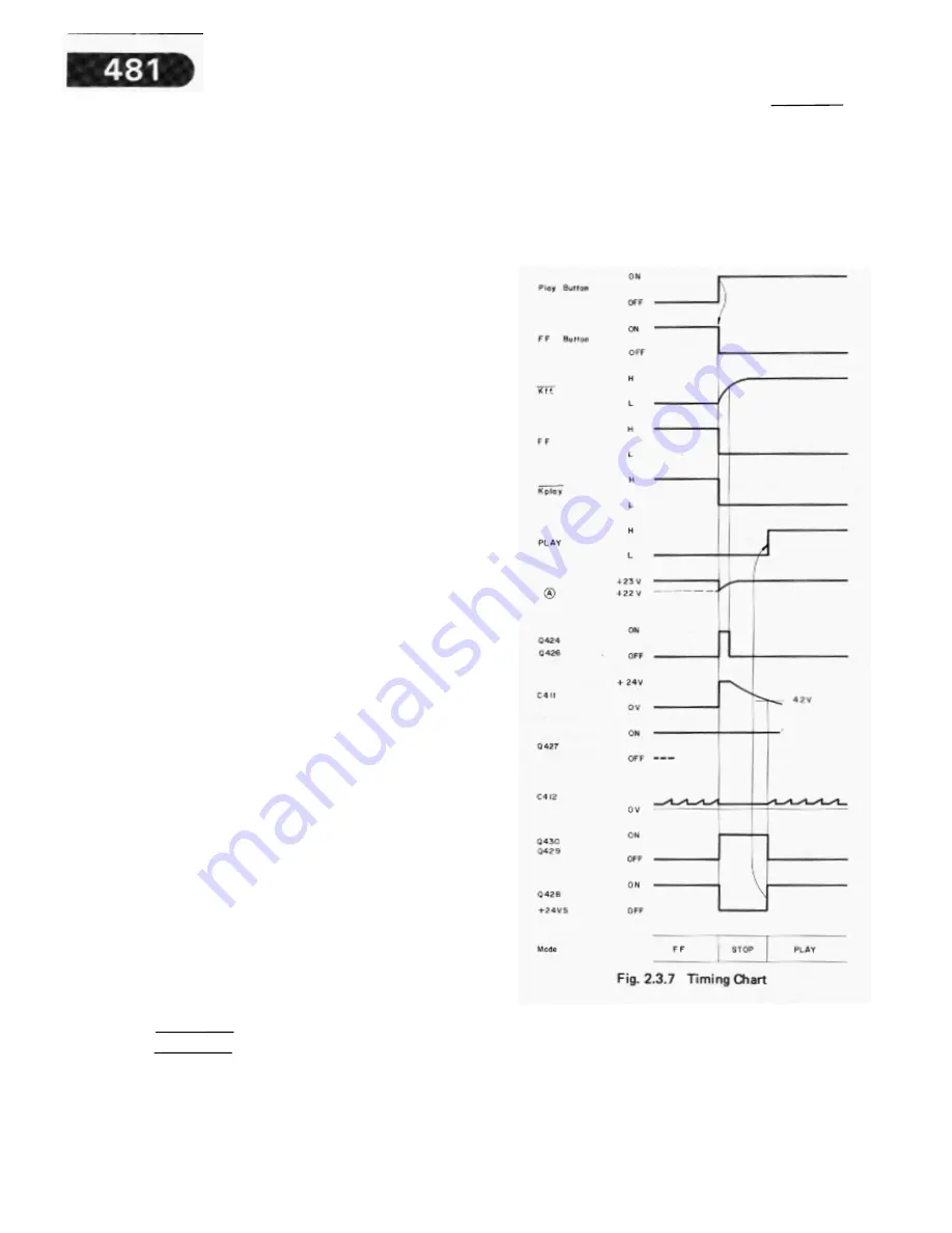
Refer to Fig. 2.3.7 timing chart.
When mode is changed from FF to REW mode, or vice
versa, or from FF to PLAY mode, momentary STOP mode
is automatically taken in view of the response of the tape
deck mechanism, and after this is over, a new mode is
set.
The following explains in regard to the case when FF
mode is changed to PLAY mode by pressing Play Button
during FF mode:
During FF mode, R486 (100 kohm) is grounded by the
NOT Kf.f. =
L signal. When Play Button is pressed, it is
locked ON and FF Button is released. Although FF Button
is re leased, the
NOT Kf.f.
signal is kept L for a short
period of time because the delay circuit (C605 and R608)
connected in parallel to FF Button acts to prolong the
NOT
k.f.f
= L signal.
In this period, the voltage at the point
A becomes approx. +22 V from +23 V pulse-likely as
R486 and R488 are grounded by the
NOT Kf.f =
L and
NOT Kplay =
L signals respectively. Consequently,
Q
424
and
Q
426 are turned ON, and C411 is charged up to +24
V, but C411 will be discharged after this period is over.
The base current to Q430 is supplied from C411 through
D424 and R475, as a result, Q430 and 0429 are turned
ON, Q428 is turned OFF, and +24 VS is shut off resulting
in STOP mode. On the other hand, since the base current
to Q427 is supplied from C411 through R469, R427 is
turned ON until the discharge of C411 is completed.
When the voltage of C411 is lower than the emitter
voltage (approx. 4.2 V) of Q430, Q430 and Q429 are cut
off, Q428 is turned ON, and +24 VS is supplied, as a
result, the PLAY signal becomes H (+24 VS) and PLAY
mode is set.
2) From RECORD mode to FF or REW mode
When mode is changed from RECORD to FF or REW
mode, momentary STOP mode is automatically taken in
view of the tape deck mechanism, and after this is over, a
new mode is set.
When Record Button is released by pressing either FF or
REW Button, Q419 is turned from ON to OFF, therefore, a
negative differentiated pulse is applied to the point A via
C421 (22 uF).
This negative pulse acts to turn ON Q424 and Q426, as a
result, C411 is charged up to +24 V. FF or REW mode is
set after passing through a certain period of STOP mode
in the same manner as above (1).
(c) Power-mute
=
L
The Power-mute
=
L pulse is generated when Power
Switch is turned ON or OFF. During the Power-mute sig
-nal is L, the voltage at the point A becomes lower than
the emitter voltage of Q424. Subsequently, Q424 and
Q426 are turned ON, C41 1 is charged up to +24 V, and
shut-off is activated in the same manner as above (b).
(d) Memory
Rewind
During REW mode and with Memory Rewind Switch
turned ON, C414 is grounded when the tape counter
comes to “999” and Q431 is turned ON pulse-likely. As a
result, Q430 is turned ON, and shut-off is activated
resulting in STOP mode.
Summary of Contents for 481
Page 1: ......
Page 4: ......
Page 17: ......
Page 20: ......
Page 22: ......
Page 36: ...6 PARTS LOCATION FOR ELECTRICAL ADJUSTMENT ...
Page 37: ......
Page 38: ......
Page 39: ......
Page 40: ......
Page 41: ......
Page 42: ......
Page 43: ......
Page 44: ......
Page 45: ......
Page 46: ......
Page 47: ......
Page 48: ......
Page 49: ......
Page 50: ......
Page 51: ......
Page 52: ......
Page 53: ......
Page 54: ......
Page 55: ......
Page 56: ......
Page 57: ......
Page 58: ......
Page 59: ......
Page 60: ......
Page 61: ......
Page 62: ......
Page 63: ......
Page 64: ......
Page 65: ......
Page 66: ......


