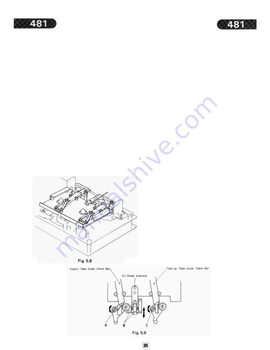
5.5. Tape Guides Adjustment and Erase Head Stroke
Adjustment
Remove Head Mount Base Ass’y. Refer to Figs. 5.8 and 59.
(1) Supply Tape Guide Height Adjustment
(a) Load an EH Stroke Check Gauge M-9042/M-9051 in
the N-481.
(b) Set the N-481 in play mode.
(c) Slide the Supply Tape Guide Check Bar down against
the supply tape guide, thus check can be made on
supply tape guide height.
(d) If the supply tape guide is misaligned, the Supply Tape
Guide Check Bar will not come into the supply tape
guide. If such is noted, turn to adjust the height
adjustment nut A till the Supply Tape Guide Check Bar
is accepted by the supply tape guide.
(e) If the above are insured, set the N-481 in pause mode,
then in play mode to see whether adjustments are
appropriately made. If not, (b) through (e) will have to
be repeated till satisfactory results are obtained.
(2) Take-up Tape Guide Height Adjustment
(a) Load an EH Stroke Check Gauge M-9042/M-9051 in
the N-481.
(b) Set the N-481 in play mode.
(c) Slide the Take-up Tape Guide Check Bar down against
the take-up tape guide, thus check can be made on
take-up tape guide height.
(d) If the take-up tape guide is misaligned, the Take-up
Tape Guide Check Bar will not come into the take-up
tape guide. If such is noted, turn to adjust the height
adjustment nut B till the Take-up Tape Guide Check
Bar is accepted by the take-up tape guide.
(e) If the above are insured, set the N-481 in pause mode,
then in play mode to see whether adjustments are
appropriately made. If not, (b) through (e) will have to
be repeated till satisfactory results are obtained.
(3) Erase Head Stroke Adjustment
(a) Load an EH Stroke Check Gauge M-9042/M-9051 in
the N-481.
(b) Set the N-481 in play mode, thus check can be made
on erase head stroke through the EH Stroke Indicator.
(c) Check to insure whether the erase head surface is
aligned with red line on the EH Stroke Indicator. If not,
adjust the erase head stroke by loosening 2 screws that
assembled erase head and erase head plate.
(d) After completion of adjustment, 2 pcs. of screws shall
be locked with lock tight paint.
Note: EH Stroke Check Gauge M-9042 (DA09042A)
should be used for the Models from serial Nos.
A30601001 to A30604798, and EH Stroke Check
Gauge M-9051 (DA09051A) is for the Models
bearing serial Nos. A30604799 and greater.
Summary of Contents for 481
Page 1: ......
Page 4: ......
Page 17: ......
Page 20: ......
Page 22: ......
Page 36: ...6 PARTS LOCATION FOR ELECTRICAL ADJUSTMENT ...
Page 37: ......
Page 38: ......
Page 39: ......
Page 40: ......
Page 41: ......
Page 42: ......
Page 43: ......
Page 44: ......
Page 45: ......
Page 46: ......
Page 47: ......
Page 48: ......
Page 49: ......
Page 50: ......
Page 51: ......
Page 52: ......
Page 53: ......
Page 54: ......
Page 55: ......
Page 56: ......
Page 57: ......
Page 58: ......
Page 59: ......
Page 60: ......
Page 61: ......
Page 62: ......
Page 63: ......
Page 64: ......
Page 65: ......
Page 66: ......


