background image

Summary of Contents for 610

Page 1: ...Nakamichi 610 Control Preamplifier Operating Instructions...

Page 2: ...Remote Control Unit 5 PrecautionS 0 eee eee eee eee 6 Using the 610 as a Preamplifier 7 8 9 Using the 610 as a Performance Checker 10 11 12 Using the 610 as aMixer 13 14 15 16 Block Level Diagrams 17...

Page 3: ...in the area of performance for many years to come Since the Nakamichi 610 offers a level of flexibility never before available on consumer electronic products its incorporation into your music system...

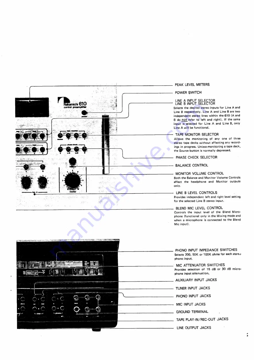
Page 4: ...es in the Mixing mode only see page 13 MASTER LEVEL CONTROL Serves as the mixer output level contro and master record level control STEREO HEADPHONE JACK PRESET MARKER Serves as a reminder when using...

Page 5: ...BALANCE CONTROL MONITOR VOLUME CONTROL Both the Balance and Monitor Volume Controls affect the headphone and Monitor outputs only LINE B LEVEL CONTROLS Provides independent left and right level setti...

Page 6: ...nnect the ground wire from the turn table to the Ground Terminal Select the appropriate input impedance with the Phono Input Impedance Switch as recommended by the manufacturer of the phono cartridge...

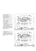
Page 7: ...the illustration Power Amplifier Tape Deck 3 The output of the tape deck should be connected to the Aux input of the 610 and the Line output of the 610 should be connected to the deck s tine inputs A...

Page 8: ...Output Selector button on the 610 is depressed the RM 610 will switch the output of the power amplifier to the selected loudspeaker system If the listen ing levels of the loudspeaker systems are to b...

Page 9: ...record player removing or installing a plug in type phono car tridge headshell turning the power on or off on electret or condenser micro phones or in general doing anything that may introduce a sudde...

Page 10: ...however as if the preamp had two selector knobs instead of one The smaller volume con trols allow adjustment of the level of the inputs selected for Line A and Line B the Blend Mic Level contro in th...

Page 11: ...Control Use the Peak Level Meters as a guide average levels should read between 10 to 0 dB Always turn the Master Level Con trol fully counter clockwise before lifting the tonearm from the record ine...

Page 12: ...e average levels should read between 10 and 0 dB 7 Turn the Monitor Volume Control to the desired listening level Note A When dubbing from one tape deck to another employ the latter method above The p...

Page 13: ...r cassette on the tape deck s record level meters Re adjust the Tone Level control on the 610 if necessary If the deck is a three head machine put the Monitor switch on the deck to the Tape position I...

Page 14: ...the Peak Level Meters The VU level meters on many open reel and cassette tape decks are not fast enough to give accurate indications of musical peaks The illustration points to the fact that there can...

Page 15: ...t the loudspeakers are connected out of phase 4 f it is determined that the loudspeak ers are out of phase with each other reverse the connections at the ampli fier or at the loudspeaker for one chann...

Page 16: ...te the Mic Attenuators with the appropriate switches on the rear panel of the 610 Note If all five microphones are not of the same manufacturer there is a remote possibility that their phase may not b...

Page 17: ...ecessary activate the Mic Attenuators for the three microphones with the ap propriate switches on the rear panel of the 610 Also check the mic phasing as described in Example 1 3 Mixing 3 Microphones...

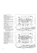
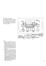
Page 18: ...are used as sources Tape Deck 3 therefore would be used to record the mix 5 Mixing 1 Record Player 1 Tape Deck and Blend Mic 1 Depress the Source button on the Tape Monitor Selector 2 Depress the appr...

Page 19: ...the Blend Mic and render the Phase Invert buttons in operative It is a good idea when making a live recording or any tape recording that is likely to be played back on a deck other than the one on whi...

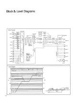
Page 20: ...t level monitor VR L monitor out t phase check poemeres ees i OL phase inverter mixing amp line out generator tevel 1 1 4 4 t T 1 n 1 1 I t t 1 H i 1 I 1 1 n audio generator test tone to remote Level...

Page 21: ...pedance 4 Poor connections at cartridge tone Check al cartridge and tonearm con arm tacts en Distortion hum or noise in Mic 1 Mic preamp overload Activate 15 dB or 30 dB Mic Attenuator as required 2 P...

Page 22: ...ophone Amp 100 200 500 2 10K 20K Frequency Hz RIAA Equalizer Amp Phono Input Impedance vs Noise Level 120d8 1 aa i S bine jh al LU o Phere ele Total Harmonic Distortion Hl il ll Input Tape PB 1 Output...

Page 23: ...2K ohms 50K ohms accuracy 20 dB to 10 dB 1 dB headphone 40 mW 8 ohms 8 200 ohms 40 dB to 20 dB 2 dB Maximum Output at Clipping frequency response sree 50 20 000 Hz 0 1 dB 30 10 dB monitor out 5V into...

Page 24: ...76 516 333 5440 144513 NAKREI CAPL NAKAMICHI RESEARCH U S A INC 1101 Colorado Avenue Santa Monica Calif 90401 Phone Telex 213 451 5901 652429 NAKRE SNM NAKAMICHI RESEARCH INC 1 153 Suzukicho Kodaira T...

Reviews: