3
•
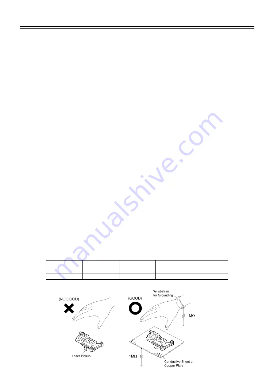
How to prevent or discharge the impressed elec-
tricity
Please refer to the following items.
1) Grounding
When you repair a laser pickup, first ground the human
body, as well as the measuring instruments and other
tools (with particular caution to the soldering iron). What's
more, your workbench and floor should desirably be
grounded using a conductive sheet or copper plate. Be
careful so as not to let your clothes touch the laser pickup,
as static electricity on the clothes may be released even
if your body is grounded.
2) Discharge of electricity
Be sure to discharge electricity from objects brought into
contact with the laser pickup (i.e., soldering iron, twee-
zers, probes, volt-ohm-meter probes, etc.) before start-
ing work by contacting them with the DVD player's chas-
sis. Also, never touch the laser pickup while power is
applied.
3) Soldering iron
The soldering iron for use in repair work should be: (1) a
ceramic soldering iron, (2) a soldering iron with its metal
part grounded, or (3) a soldering iron whose insulation
resistance after power application is 10 M-ohm or more
at 500 VDC. Soldering should be completed promptly,
at a soldering iron temperature of 320
°
C ideally. (39W).
A soldering iron heated above this temperature can break
down the laser diode.
GENERAL
1.4 Caution for handling Laser Pickup of DVD Player
[Electric Influence because of impressed electricity]
Laser pickup of a DVD player is weaker and more sen-
sitive than that of CD player, it is possible to damage
the pickup under specific electrical environments, such
as impressed or leaked electricity, including static elec-
tricity. Electricity that is impressed during modification
for zone coding, or through updating the micro proces-
sor and so forth, may influence the laser pickup.
Prevention of Impressed Electricity
•
In general
It is very difficult to specify why and how static electric-
ity is impressed. It is important to thoroughly ground
the working bench and fasten the antistatic electricity
wrist band, as well as carry out the daily management
of isolating the resistor of the soldering iron and the
leaked current in the working room.
Unfortunately, it is impossible for us, even as the sup-
plier, to assure that all these conditions are met at any
distributor or subsidiary that does not have an identical
situation to that of the manufacturing site. Consequently,
we do not recommend any modification for zone cod-
ing, that can be a negative factor against quality assur-
ance, and we consider pickup failure of any unit modi-
fied for zone coding to be out of warranty.
Note:
A precise digital tester is needed to measure the leaked current.
Condition of Soldering lron
Type
Output Wattage
Tip Temperature
Isolated Resistance
Leaked Current
For IC or LSl
13-18W
300
±
40
°
C
≥
100M
Ω
≤
1.0
µ
A
For Elec. Part
23-30W
360
±
40
°
C
≥
50M
Ω
≤
2.0
µ
A
Summary of Contents for DVD-15
Page 14: ...14 MECHANICAL ASS Y AND PARTS LIST 4 2 Mechanism Ass y DVD 15 A01 Fig 4 2...
Page 17: ...17 MECHANICAL ASS Y AND PARTS LIST 4 4 Loading EX Ass y ADJ 3 B02 Fig 4 4...
Page 51: ...To Digital PCB P550 DVD 15 MECHANISM C3M1 SCHEMATIC DIAGRAM...
Page 52: ......
Page 53: ......
Page 54: ......
Page 55: ......
Page 56: ......
Page 57: ......
Page 58: ......
Page 59: ......
Page 60: ......
Page 61: ......
Page 62: ......


