1-5
SS-9 Main Unit Section
1.7. CD P.C.B. Ass'y and Traverse Mecha Ass'y
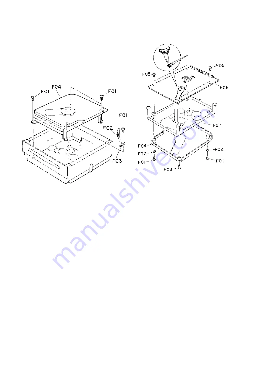
Refer to Figs. 1.7.1 and 1.7.2.
(1)
Remove the Mechanism Chassis Block. Refer to item
1.5.
(2)
Remove screws F01 (M3x5 + Binding (Black), 4 pcs.),
F02 (Stabi SP) and F03, and detach F04 (Traverse
Mechanism Block). Refer to Fig. 1.7.1.
(3)
Remove screws F01 (M2.6x4 + Binding (Black), 3
pcs.), collars F02 (3 pcs.) and one screw F03 (M2.6x4
+ Pan (Black)), and detach F04 (Traverse Cover CD).
Refer to Fig. 1.7.2.
(4)
Short the laser diode shorting lands with a soldering
iron.
Note: Use the soldering iron whose metal part is
grounded or a ceramic soldering iron.
CAUTION: Do not disconnect the Flexible Cable from
the CD P.C.B. Ass'y unless the laser short-
ing lands are shorted.
(5)
Remove screws F05 (M3x5 + Binding), 4 pcs.) and de-
tach F06 (CD P.C.B. Ass’y).
(6)
Remove three Damper Screw SL and one Damper
Screw SD, and detach F07 (Traverse Mecha Ass'y).
Notes on reassembling:
• Unsolder the laser diode shorting lands after reassem-
bling the CD P.C.B. Ass'y.
Fig. 1.7.1
Fig. 1.7.2
Laser diode shorting lands
CD P.C.B. Ass’y
Traverse Mecha
Ass’y
Traverse Mechanism Block
Summary of Contents for SoundSpace 9
Page 37: ...SS 9 Main Unit Section 1 32 Fig 6 6 BLOCK DIAGRAM...
Page 38: ...2 1 SS 9 Subwoofer Section Subwoofer Subwoofer Section...
Page 45: ...3 1 SS 9 Satellite Speaker Section Satellite Speaker Section Satellite Speaker...
Page 52: ...SS 9 SS 9 SS 9 SS 9 1 4 SS Main Unit Section Main P C B Ass y...
Page 53: ...SS 9 SS 9 SS 9 SS 9 2 4 Main Unit Section CD P C B Ass y...
Page 54: ...SS 9 SS 9 SS 9 SS 9 3 4 Main Unit Section Front P C B Ass y...


