2-2
SS-9 Subwoofer Section
1
2
1
2
1
2
CONTENTS
1.
ELECTRICAL ADJUSTMENTS
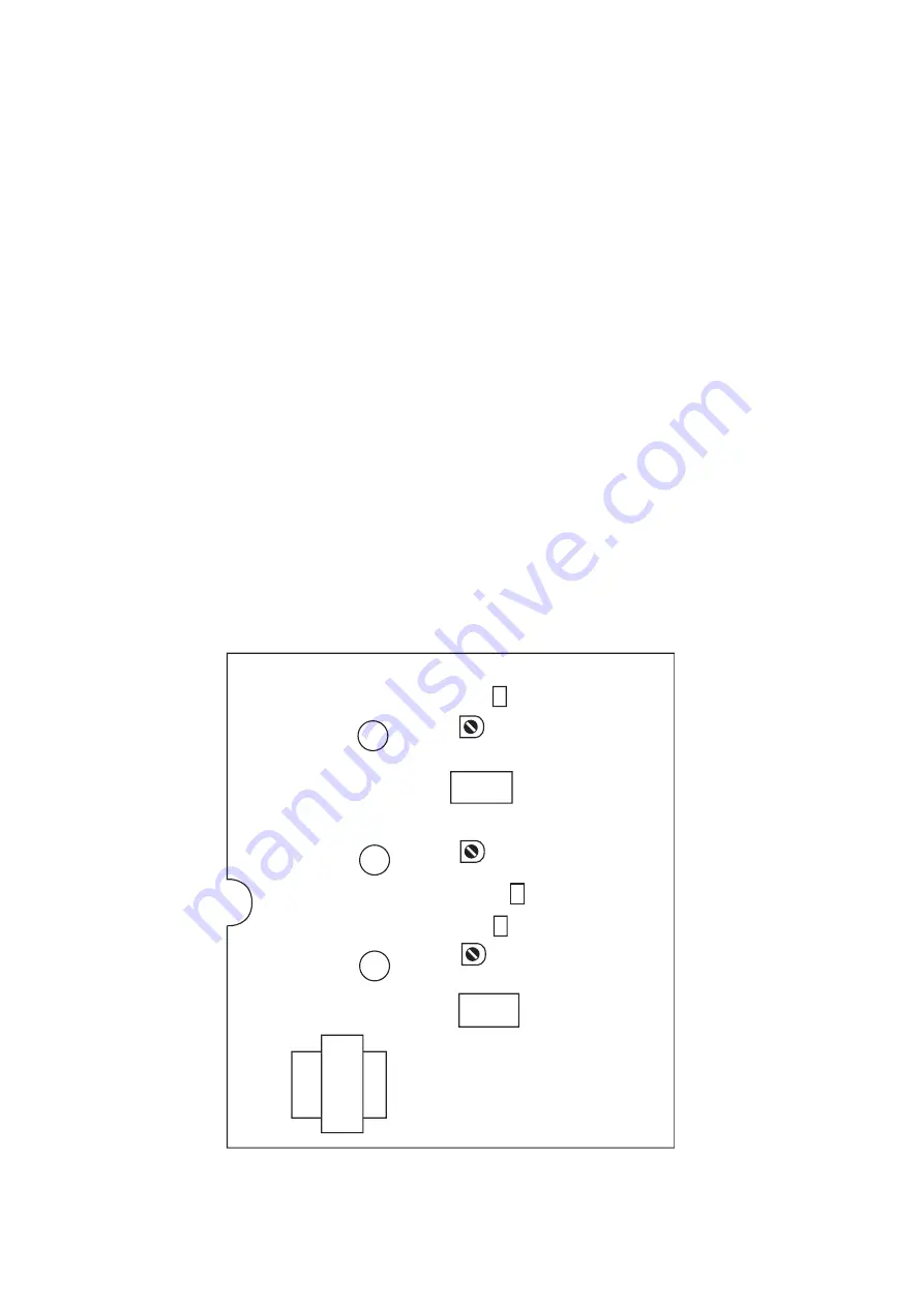
1.1. Parts Location for Electrical Adjustment
Fig. 1.1
Idling Current — Lch
VR101
Idling Current — Subwoofer
VR701
TP101
TP701
TP201
PST P.C.B. Ass’y
Idling Current — Rch
VR201
1.
ELECTRICAL ADJUSTMENTS .........................................................................................................................2-2
1.2.
Adjustment Procedure ...........................................................................................................................2-3
2.
MECHANISM ASS'Y AND PARTS LIST ...........................................................................................................2-4
2.1.
Synthesis (Subwoofer) ...........................................................................................................................2-4
2.2.
PA Chassis Ass'y (A01) ........................................................................................................................2-5
3.
ELECTRICAL PARTS LIST ...............................................................................................................................2-6
3.1.
AMP P.C.B. Ass'y ..................................................................................................................................2-6
3.2.
REM P.C.B. Ass'y ..................................................................................................................................2-6
3.3.
Input P.C.B. Ass'y ..................................................................................................................................2-6
3.4.
PS P.C.B. Ass'y ..................................................................................................................................... 2-7
3.5.
PST P.C.B. Ass'y ................................................................................................................................... 2-7
3.6.
SP4P P.C.B. Ass'y .................................................................................................................................2-7
3.7.
T.PRI P.C.B. Ass'y .................................................................................................................................2-7
3.8.
T.SEC P.C.B. Ass'y ................................................................................................................................2-7
3.9.
Inlet P.C.B. Ass'y ................................................................................................................................... 2-7
3.10. VR P.C.B. Ass'y ..................................................................................................................................... 2-7
SPECIFICATIONS (See the end of this manual.)
SCHEMATIC DIAGRAM AND MOUNTING DIAGRAMS (See the separate volume.)
Summary of Contents for SoundSpace 9
Page 37: ...SS 9 Main Unit Section 1 32 Fig 6 6 BLOCK DIAGRAM...
Page 38: ...2 1 SS 9 Subwoofer Section Subwoofer Subwoofer Section...
Page 45: ...3 1 SS 9 Satellite Speaker Section Satellite Speaker Section Satellite Speaker...
Page 52: ...SS 9 SS 9 SS 9 SS 9 1 4 SS Main Unit Section Main P C B Ass y...
Page 53: ...SS 9 SS 9 SS 9 SS 9 2 4 Main Unit Section CD P C B Ass y...
Page 54: ...SS 9 SS 9 SS 9 SS 9 3 4 Main Unit Section Front P C B Ass y...


