background image

SS-9 General

v

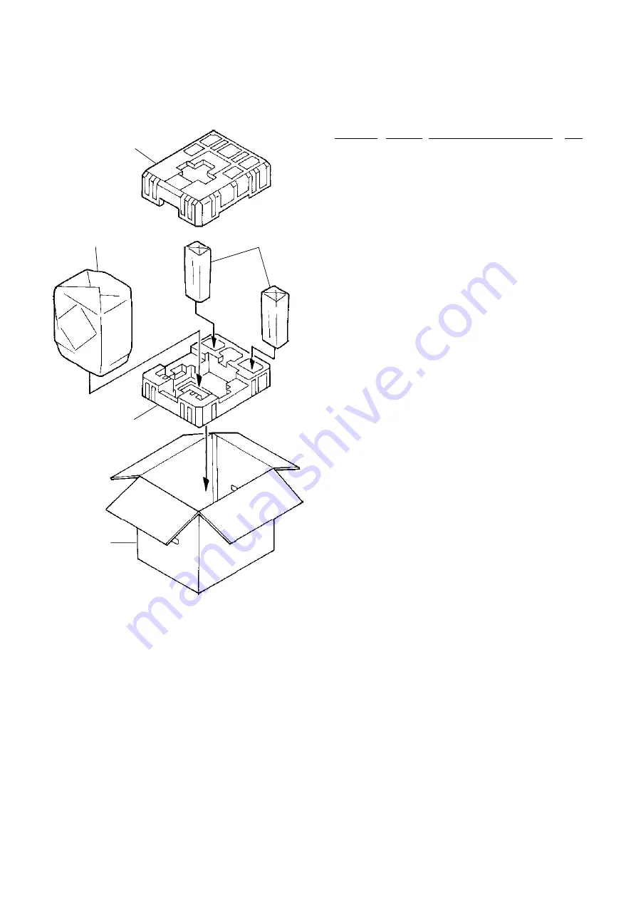
(2)  Subwoofer and Satellite Speakers

Fig. 1.4  Subwoofer and Satellite Speakers

      —

Package and Accessory Ass’y
(Subwoofer and Satellite Speakers)

01

0F05694A

Carton Box S369

1

02

0F05703A

Packing Bottom Subwoofer

1

03

0F05702A

Packing Top Subwoofer

1

04

0F05691A

Soft Sheet Subwoofer

1

05

0F05541A

Soft Bag Satellite

2

DA05647A Screw Ass’y S369

1

DA05648A Spacer Ass’y S369

1

Schematic
Ref. No.

Part No.

Description

Q'ty

01

04

05

02

03

Summary of Contents for SoundSpace 9

Page 1: ...SS 9 General i Service Manual Service Manual Stereo Music System SoundSpace 9 ST Preset FM AM Disc Track Remaining Time Memory No Memory Repeat Random Loud Vol...

Page 2: ...ord is less than 240 k ohms the unit is defec tive WARNING DO NOT return the unit to the customer until the problem is located and corrected 3 Protection of Eyes from Laser Beam To protect eyes from i...

Page 3: ...e released even if your body is grounded THIS COMPACT DISC PLAYER IS CLASSIFIED AS A CLASS 1 LASER PRODUCT THE CLASS 1 LASER PRODUCT LABEL IS LOCATED ON THE REAR EXTERIOR CLASS 1 LASER PRODUCT 2 Disch...

Page 4: ...rd DA DU OTR DA TW 1 0D07241A AC Cord DM JPN 1 0D07242A AC Cord BS HK UK HK 1 0D07243A AC Cord CH CH 1 0D07244A AC Cord KR KR 1 0D07245A AC Cord SA AUS 1 0D07371B Owner s Manual Japanese 1 0D07372B Ow...

Page 5: ...Subwoofer and Satellite Speakers 01 0F05694A Carton Box S369 1 02 0F05703A Packing Bottom Subwoofer 1 03 0F05702A Packing Top Subwoofer 1 04 0F05691A Soft Sheet Subwoofer 1 05 0F05541A Soft Bag Satell...

Page 6: ...1 1 SS 9 Main Unit Section Main Unit Main Unit Section ST Preset FM AM Disc Track Remaining Time Memory No Memory Repeat Random Loud Vol...

Page 7: ...lectrical checks for CD Player 1 9 3 MECHANISM ASS Y AND PARTS LIST 1 11 3 1 Main Stand Ass y 1 11 3 2 Synthesis Main Unit 1 12 3 3 Mechanism CD Ass y 1 Mechanism CD Ass y 2 A01 1 14 3 4 Mechanism Cha...

Page 8: ...and 3 to the connectors 1 2 and 3 on the Main P C B Ass y respectively 1 3 Mechanism CD Ass y Refer to Fig 1 3 1 Remove the Main P C B Ass y Refer to item 1 2 2 Remove screws F01 M3x8 Binding 2A 8 pc...

Page 9: ...pcs and detach F11 Front P C B Ass y Notes on reassembling When assembling F08 Power Switch be careful so as not to assemble it upside down When assembling F07 pass the power switch cable through the...

Page 10: ...2 4 Short the laser diode shorting lands with a soldering iron Note Use the soldering iron whose metal part is grounded or a ceramic soldering iron CAUTION Do not disconnect the Flexible Cable from th...

Page 11: ...Refer to item 1 7 2 Remove screws F01 M1 7x4 Pan 2 pcs and F02 M2 6x3 5 Pan 2 pcs and F03 4 pcs and disas semble F04 Laser Pickup Block 3 Pull out the PU Guide Shaft SL from the Laser Pickup Block 4...

Page 12: ...wn in Fig A 4 Assemble the UD Cam on the chassis so that its rack engages with the gear on the chassis Then by turn ing the Cam Drive Gear on the chassis align the edge of the UD Cam with the edge of...

Page 13: ...s 1 Oscilloscope 40 MHz or more 2 DC Voltmeter Digital Voltmeter 3 ABEX Test Disc TCD 784 DA09195A 4 ABEX Test Disc TCD 726A DA09204A or TCD 725A 2 2 Parts Location for Electrical Check CD P C B Ass y...

Page 14: ...current value IOP shown on the label are almost the same How to read IOP on the label The shaded OOO on the label shows the IOP If OOO is 475 the IOP is 47 5mA NOTE The calculated current I Measured s...

Page 15: ...isc Check TCD 726 or TCD 725A Make sure that no noise nor track jumping is found in the following programs on the test disc To select the desired program press Track Search button on the Main Unit or...

Page 16: ...t 1 01 0J08792A Base Cushion Center S 2 02 0H08793B Stand Base Center R 1 03 0H08792B Stand Base Center L 1 04 0H08791D Base Joint 1 05 0H08796B Stand Pole 1 06 0H08790C Stand Holder Center 1 L01 0E04...

Page 17: ...y 2 A01 02 Mechanism CD Ass y 1 A01 01 06 04 05 06 09 L01 L01 L03 L03 15 L03 L02 L15 16 11 12 06 07 L02 L03 08 14 17 18 19 10 20 L05 L02 L06 L05 L06 L05 L06 L12 L14 L07 L06 L12 L06 L17 L07 L07 L07 L0...

Page 18: ...ini Jack Plate A 1 18 0H07947D Mini Jack Cover 1 19 0J08279A Mini Jack Cover SP 1 20 BK10318A Main P C B Ass y DM JPN 1 BK10319A Main P C B Ass y UL 1 USA CAN DA TW BK10320A Main P C B Ass y EP 1 UK A...

Page 19: ...Mechanism CD Ass y 1 Mechanism CD Ass y 2 A01 Fig 3 3 01 02 L01 Disc Loading Ass y B03 07 04 06 03 05 L02 L02 Traverse Mecha Ass y B02 12 08 10 L04 09 11 13 16 L05 L06 L06 L05 L07 L07 Mechanism Chassi...

Page 20: ...ding L07 0E03950A M2 6x5 Binding L08 0E00174A Earth Lug B 4 L09 0E04308A M2x3 5 Pan 0 Type 3 Schematic Ref No Part No Description Q ty 3 3 Mechanism CD Ass y 2 A01 A01 Mechanism CD Ass y 2 1 01 HG0854...

Page 21: ...m Roller 6 3 4 Mechanism Chassis Ass y B01 Fig 3 4 Schematic Ref No Part No Description Q ty 19 0C10514A UD Cam Roller S 2 20 0C10265A Motor Grommet SL 1 L01 0E03270A M3x5 Binding Black L02 0E04085A M...

Page 22: ...up KSS 540A 1 12 0B61355A Pick up Flexible P C B 1 Apply lubricant G 4270 13 0C10278A Shaft Lock Plate SL 4 14 0C10282A PU Guide Plate H SL 1 15 0C10138B First Gear 1 L01 0E04343B Cut Washer 1 6x3 2x0...

Page 23: ...14 L12 L17 11 09 L04 25 L11 26 L13 29 L01 30 31 32 33 L13 35 34 11 L12 L10 L16 L02 L15 L02 L11 21 22 23 26 47 39 38 37 L14 48 49 51 50 40 41 44 36 L10 43 45 42 52 28 L02 L08 L07 L09 L06 L10 15 53 54...

Page 24: ...Pulley Fork SL 1 39 0C10193A Pulley Spring SL 1 40 0C10476B LDG Guide R SD 1 41 0C10477A Timing Belt SD 1 42 0C10213A Timing Gear SL 1 43 0C10478A Loading Link B SD 1 44 CA09465A Loading Link A S Ass...

Page 25: ...TR DTC144EK Q526 0B14011A TR DTC114EK Q601 0B14002A TR DTA114EK Q602 0B14013A TR DTC144EK Q603 0B14004A TR DTA144EK Q604 0B14002A TR DTA114EK Q605 0B14013A TR DTC144EK Q606 0B14167A TR 2SC2412K Q607 6...

Page 26: ...8 Q403 0B10901A TR 2SD2153TL Q404 0B10930A TR 2SD1758F Q411 412 0B14167A TR 2SC2412K Q413 0B14167A TR 2SC2412K Q414 0B10930A TR 2SD1758F Q501 502 0B14013A TR DTC144EK Q503 504 0B12847A TR 2SK2158 Q505...

Page 27: ...ing 18 CD SCK I Serial clock input from the CD Mechanism L H L Serial clock input for flash ROM writing 19 CD3RES O Reset signal to the Mechanism CD Ass y No 3 H L 20 CD2RES O Reset output to the Mech...

Page 28: ...54 T EN O Communication permit output between the PLL IC H L 55 NC Not used 56 SD I SD input from the PLL IC L 57 ST I Stereo input from the PLL IC L 58 SYNC I RDS sync input L 59 RDSID I RDS ID input...

Page 29: ...P47 Not used 18 DISCIN I Mechanism loading sensor input 19 P51 Not used 20 UD I Mechanism Up Down sensor input 21 HOME I Mechanism Up Down sensor input 22 LDLOAD O Mechanism loading motor drive output...

Page 30: ...ACK OUT 61 P24 Not used 62 SQSO IN DSP SubQ data input 63 P26 Not used 64 SQCK O DSP SQSO readout clock H L L Mechanism Controller Continued U501 PD78018FGC A B 8 V OUTPUT B 7 6 5 4 3 2 1 OUTPUT A V T...

Page 31: ...R4 25 RCOM2 24 R5 23 R6 22 RCOM3 21 R7 20 RCOM4 14 DI 15 CL 13 CE 2 L2 4 L3 5 L4 6 LCOM2 7 L5 8 L6 9 LCOM3 10 L7 11 LCOM4 19 VDD 16 VSS 12 VEE 18 RES 17 S 3 LCOM1 28 RCOM1 Function Switch LC78213 U204...

Page 32: ...LD1 6 L LD2 7 L A GND 8 NC 9 CS1 10 NC 11 NC 12 GND 13 CK 14 VR 50K 91STEP LEVEL SHIFT CK 8 20 BIT SHIFT REGISTER ANALOG SWITCH ANALOG SWITCH LADDER RESISTORS LADDER RESISTORS ANALOG SWITCH LADDER RE...

Page 33: ...VO2 VO1 VO1 VO4 VO4 VO3 VO3 POWVCC2 STBY2 GND OPOUT3 OPOUT4 OPIN3 OPIN3 OPIN4 OPIN4 PREVCC Driver BA5983FP U104 REFERENCE VOLTAGE VREF 1 FLOUT 5 CIN 6 ANTIALIASING FILTER 67KHz BPF SCF SMOOTHING FILT...

Page 34: ...5 RFO 26 RF M 27 VCC 28 LD ON 29 LD 30 PD 31 A 32 B 10K 10K 10K 10K VC 4K VC 36 7K VC 160K 32K 26K 130K 80K 8K 4K 15K 1K 60K 2K VC 39K 7 5K 32K 75K 39K 44K 18K 80K 80K 20K 20K 54K 40K 92K 20K 15K 15K...

Page 35: ...ERROR 16 DATAO 45 DOSEL1 13 CKOUT 14 BCK 15 LRCK 47 CKSEL1 40 MODE0 41 MODE1 48 XMODE Digital Audio Interface Receiver LC89055W U803 SERIAL DATA INTERFACE ATTEN MUTE ATTEN MUTE 8 x INTERPOLATOR 8 x IN...

Page 36: ...L SUB CODE PROCESSOR 16K RAM ASYMMETRY CORRECTOR CLOCK GENERATOR EFM DEMODULATOR DIGITAL OUT 19 C2PO 61 LRCK 62 PCMD 63 BCK 16 XUGF 18 GFS 64 EMPH 15 WFCK 37 XTSL 51 RFAC 49 ASYI 48 ASYO 50 BIAS 17 XP...

Page 37: ...SS 9 Main Unit Section 1 32 Fig 6 6 BLOCK DIAGRAM...

Page 38: ...2 1 SS 9 Subwoofer Section Subwoofer Subwoofer Section...

Page 39: ...ocedure 2 3 2 MECHANISM ASS Y AND PARTS LIST 2 4 2 1 Synthesis Subwoofer 2 4 2 2 PA Chassis Ass y A01 2 5 3 ELECTRICAL PARTS LIST 2 6 3 1 AMP P C B Ass y 2 6 3 2 REM P C B Ass y 2 6 3 3 Input P C B As...

Page 40: ...on the Subwoofer unit 2 Remove the PA Chassis 3 Turn ON the power of the Subwoofer unit and allow 15 minutes before starting adjustment 1 Connect the DC milli voltmeter between pins of TP101 2 Adjust...

Page 41: ...ubwoofer 01 CB00729A Subwoofer Grille Ass y 1 02 CB00627A Subwoofer Speaker S800L05 1 03 0H08368D Power Amp Cover 1 04 PA Chassis Ass y Subwoofer 1 CB00634A Cord Ass y Woofer 1 L01 2E00133A Tapping 4x...

Page 42: ...wer Transformer EP 1 UK AUS EP CH HK KR 0B50370A Power Transformer UL USA CAN 1 0B50472A Power Transformer DU DA OTR DA 1 07 BK10338A T SEC P C B Ass y CE 1 UK AUS EP CH HK KR BK10339A T SEC P C B Ass...

Page 43: ...249A SID 1SS133 D407 0B12249A SID 1SS133 D501 502 0B12249A SID 1SS133 D503 504 0B12249A SID 1SS133 D505 0B12249A SID 1SS133 D601 0B12249A SID 1SS133 D701 702 0B12249A SID 1SS133 D703 0B12249A SID 1SS1...

Page 44: ...K AUS EP CH HK KR CN611 0B85354A 4P Speaker Terminal 3 7 T PRI P C B Ass y BK10336A T PRI P C B Ass y CE UK AUS EP CH HK KR BK10337A T PRI P C B Ass y Except CE JPN OTR USA CAN DA TW F401 0B90830A Fus...

Page 45: ...3 1 SS 9 Satellite Speaker Section Satellite Speaker Section Satellite Speaker...

Page 46: ...Ass y 1 02 CB00638A Satellite Tweeter 1 03 CB00637A Satellite Woofer Speaker S350F02 2 04 0H08822C Stand Holder Speaker 1 05 0J08722A S Holder Fix Plate 1 06 0H08796B Stand Pole 1 07 0H08791D Base Joi...

Page 47: ...l 1 kHz 65 dBf Modulation MONO 100 Stereo Pilot 10 audio 90 RF Frequency USA CAN OTR EP 98 1 MHz JPN 83 0 MHz Tuning Range USA CAN 87 5 107 9 MHz 200 kHz steps JPN 76 0 90 0 MHz 100 kHz steps OTR EP H...

Page 48: ...ter 50 Hz More than 15 dB 3 kHz More than 18 dB Seek Stop Level Within 45 dB V to 66 dB V Pre Amplifier Section Standard Test Condition S T C Signal 1 kHz Input AUX 200 mV Output Pre out 1000 mV Sensi...

Page 49: ...t Sensitivity at Rated Power Satellite 850 mV 2 dB Subwoofer 1100 mV 2 dB Satellite Speaker Unit Enclosure 2 way sealed type Speaker Unit Midrange Woofer 8 cm round cone 2 Tweeter 2 5 cm semi dome Imp...

Page 50: ...73 H 260 D mm 13 1 16 W 46 3 16 H 10 1 4 D inches Mass Main Unit Approx 10 kg 22 lbs 1 oz Main Unit with tabletop stand Approx 11 5 kg 25 lbs 6 oz Main Unit with floor stand Approx 14 kg 30 lbs 14 oz...

Page 51: ...are subject to change for further improvement without notice G 00120PA 0Q06270A Nakamichi Corporation 1 153 Suzukicho Kodaira Tokyo 187 8501 Japan Phone 81 42 342 1111 Nakamichi America 18375 S Broad...

Page 52: ...SS 9 SS 9 SS 9 SS 9 1 4 SS Main Unit Section Main P C B Ass y...

Page 53: ...SS 9 SS 9 SS 9 SS 9 2 4 Main Unit Section CD P C B Ass y...

Page 54: ...SS 9 SS 9 SS 9 SS 9 3 4 Main Unit Section Front P C B Ass y...

Page 55: ...SS 9 SS 9 SS 9 SS 9 4 4 Subwoofer Section...

Reviews: