17
15
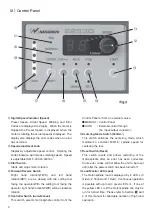
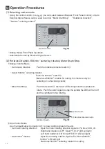
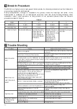
(1)WARNING Function
Always check the control unit, motor, spindle and the condition of the cooling air prior to use. This
will help prevent system errors that will result in undesired operating conditions.
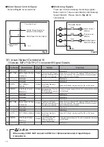
・The WARNING LED ⑳ will flash.
・The WARNING Code(listed in Table1) will be displayed on the Digital Speed Indicator ⑪.
・A WARNING Signal is output to the WARNING Signal(PIN No. 20:WARNING) of Input/Output
Connector A.
Note : When using the Input/Output Connector and external monitoring, please check and resolve the
source of the trouble anytime a Warning Code is displayed.
WARNING Code
A 0
A 1
A 3
Warning Function
Motor Cord
Low Air Pressure
Over Load
Trouble
Motor Cord or Connector is disconnected or misaligned
Low Air Pressure
Motor Torque load exceeding safe limits
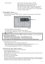
(2)Detection of unsafe operating conditions
Always check the control unit, motor, spindle and the condition of the cooling air prior to use. This
will help prevent system errors that will result in undesired operating conditions.
・Motor stops
・The Error LED⑲ will flash.
・Error Code (listed in Table2) will be displayed on the Digital Speed Indicator⑪.
・An Error signal is output to the Error Signal(PIN No.8:ERR) of Input/Output Connector A.
Table 1
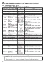
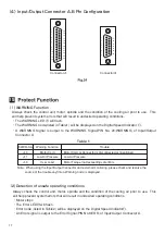
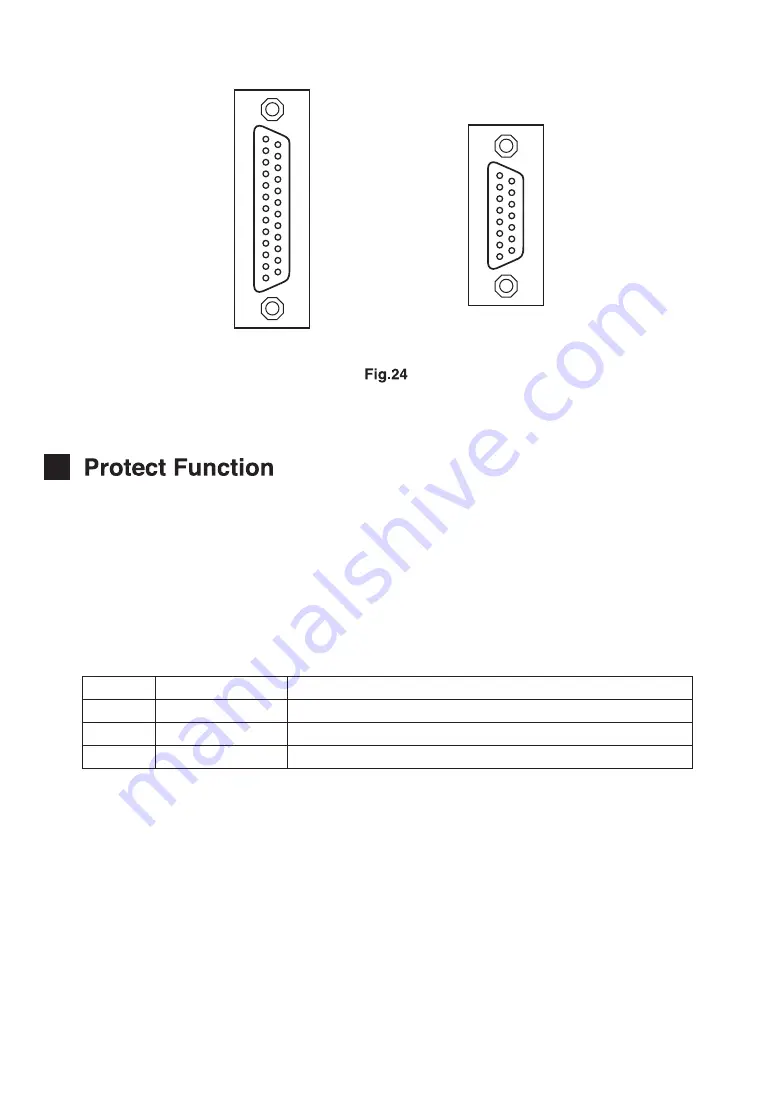
(4)Input/Output Connector A,B Pin Configuration
1
2
3
4
5
6
7
8
9
10
11
12
13
14
15
16
17
18
19
20
21
22
23
24
25
1
2
3
4
5
6
7
8
9
10
11
12
13
14
15
ConnectorA
ConnectorB


