background image

20

19


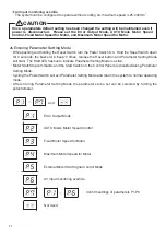
The following operating parameters can be preset depending on the application requirements.  The op-
erating parameter presets are retained in non-volatile memory and will be maintained even if power is 
disconnected. 

18


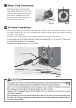
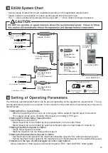
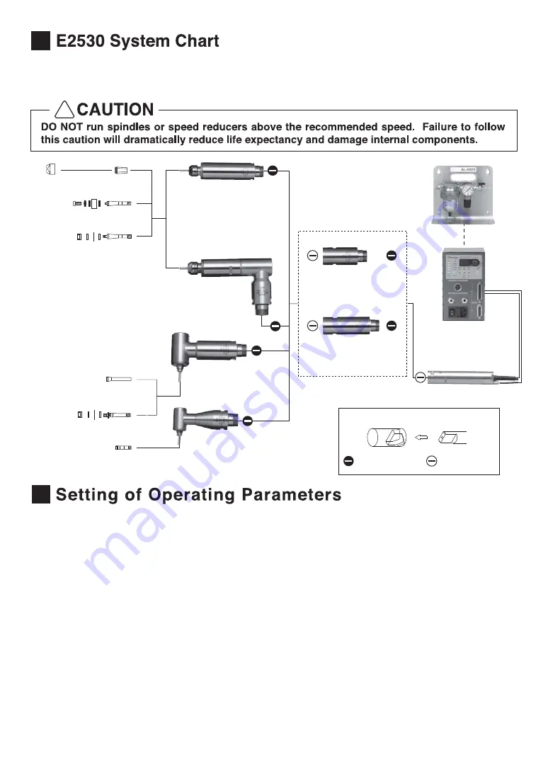
・A wide variety of attachments are available depending on the application requirements 
・Speed reducers are available to reduce spindle speed and increase torque. 
・The (−) drive spindles were designed to be used with (−) drive motors and speed reducers.

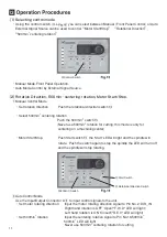
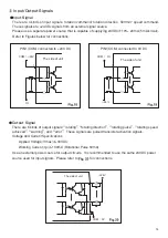
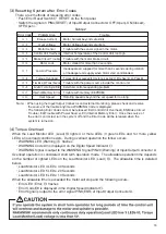
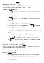
①Setting the Error Output Mode 

 ・When an operating error occurs, an error signal will be output to Input/Output Connector A.    
  This output can be set to normally ON(Closed) or normally OFF(Open). 

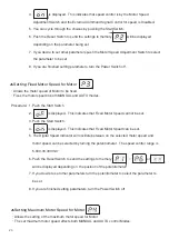
②Setting AUTO Mode Motor Speed Control 

 Control Mode is set to AUTO 
 ・Motor Speed can be controlled by the potentiometer on the Control Panel. 
 ・Motor Speed can be controlled by external command signal to Input/Output Connector A. 

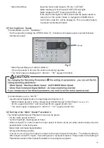
③Setting Fixed Motor Speed for Motor 

 ・Single Motor Speed is desired. 
 ・Machine Operator can not change motor speed. 

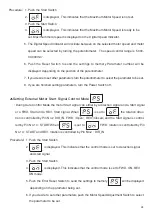
④Setting the Maximum Motor Speed for Motor 

 ・Set maximum motor speed to the maximum allowable speed for the cutting tools being used. 
 ・Set the maximum motor speed to the maximum recommended speed for the spindle being used. 

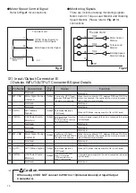
⑤Selection of the type of external signal for motor start method 

 Allows selection of Start signal and Direction Signal or REV. Start and FWD. Start signals.

! 

Chuck CHK-□□ 

Chuck Nut 

K-265

Grindstone AGM-03

Collet Chuck CH8-□□ 

Control Unit NE236

Motor EM25-5000

Spindle NR-303

Air Line Kit 
AL-0201

Axis for Metal Saw KCH-03

90°

 Angle Spindle  

RAS-101

Axis for Metal Saw KCH-02

Collet Chuck CHS-□□ 

90°

 Angle Spindle 

RA-100 
(1/2.67 Reduction)

90°

 Angle Spindle 

RA-200 
(1/1.5 Reduction)

Speed Reducer 
ARG-01 
(1/4 Reduction)

Speed Reducer 
ARG-02 
(1/16 Reduction)

Transmission Clutch

The connection part 

− is concave  

The connection part 

− is convex  

Summary of Contents for E2530 SYSTEM

Page 1: ...g Fuses 9 Power Cord Connection 10 Bracket Installation 11 Motor Cord Connection 12 Air Hose Connection 13 Operation Procedures 14 External Input Output Control Signal Specifications 15 Protect Function 16 Break In Procedure 17 Trouble Shooting 18 E2530 System Chart 19 Setting of Operating Parameters 2 3 3 4 4 6 7 8 8 9 10 10 11 13 17 19 19 20 20 INSTRUCTIONS AND WARNING Electric Devices 1 ...

Page 2: ...is tool is intended for use on a circuit that has an outlet that looks like the one illustrated in Sketch A in Figure below 115V The tool has a grounding plug that looks like the plug illustrated in Sketch A in Figure below 8 For Installation in Machine Electrical Cabinet or when wiring directry to machine internal power terminal strip 1 Prease refer to the pin diagram below for the proper wiring ...

Page 3: ...ed spindle system E2530 The E2530 System was designed for use on CNC lathes robots NC lathes and special purpose machines The motor spindle and control unit are designed to work as an integrated system capable of 5 000 30 000min 1 This system utilizes air to cool the motor and protect the spindle please use an airline kit to ensure clean dry properly regulated air is supplied to the motor and spin...

Page 4: ...ng grinding or other similar application A high speed brushless motor is used to achieve a maximum speed of 30 000min 1 and eliminate the nuisance of brush maintenance Speed control and protection functions utilize a high performance microprocessor Automatic control and monitoring of spindle functions are possible Wide speed range 5 000 30 000min 1 makes high precision machining possible Compact c...

Page 5: ...ate air to between 0 15MPa 0 25MPa Air must be supplied to operate the system Cooling air output joint for motor Connect 4 air hose from motor to output joint using 4 to 6 adaptor If this position is not being used please install the air plug to prevent contamination Input Output Connector A Connector for automatic control and monitoring of motor spindle system When not in use please install the c...

Page 6: ...ckwise rotation Controller Switch Auto Manual This switch selects motor spindle control from the Control Panel or from an external source MANUAL Control Panel AUTOqq External control through the input output connector Centering Mode Switch 500min 1 This switch activates the centering mode which maintains a constant 500min 1 spindle speed for centering the tool Reset Switch Reset This switch resets...

Page 7: ...nitored and the warning LED blinks when a hazardous condition has been detected When a hazardous condition is detected the warning LED blinks and the Digital Speed Indicator alternates between the warning code and the actual or preset speed depending on whether or not the motor spindle is rotating 1Rotating LED RUN When the motor is rotating this LED will flash Mounting brackets are provided for m...

Page 8: ...in power switch on the control unit to OFF Disconnect the main power cord from the electrical outlet Input Voltage Supply 120V Input Voltage Supply 230V Fuse T3 15A 250V Order No U195 152 Fuse T1 6A 250V Order No U197 152 Move the Voltage Selection Switch to the right hand position Move the Voltage Selection Switch to the left hand position Refer to Changing Fuses Refer to Changing Fuses Concave C...

Page 9: ...fuses depending on the input power source voltage 115V T3 15A 250V U195 152 230V T1 6 A 250V U197 152 Replace the fuse holder containing the fuses into the fuse inlet box and make sure it snaps in place Insert the female plug into the main power inlet box in the front of the unit A screw hole is provided on the lower right side of the control unit for attaching the tension relief Use the provided ...

Page 10: ...the brackets using the six holes on the bottom of the unit using the provided screws Attach the brackets using the six holes on the back of the unit using the provided screws Bottom Installation When installing 2 or more control units in the machine cabinet make sure to check that each single control unit has the proper clearance on all sides Proper Clearance Bracket Back Side Installation Bracket...

Page 11: ...ose into the output joint on the front of the control unit using the provided 6 to 4 adaptor Regulate air pressure between 0 15 0 25 MPa 11 Align the guide pin A on the motor plug with the key way B on the motor socket on the front of the control unit Screw in the coupling nut C of the motor plug to the motor socket D on the front of the control unit C D A B Air Hose with filter Air Hose with filt...

Page 12: ...g this mode is only for centering on a machining center Motor Start Stop Push Start switch the Start LED will light and the spindle will rotate Push the switch again to stop the spindle the LED will turn off and the spindle will stop rotating Control Switch 500min 1 Switch Rotational direction Switch Start Switch Auto Control Mode Use the Input Output Connector A to input control signals to the un...

Page 13: ... is set to AUTO Input External Signal Source to Input Output Connector A Motor rotation speed is set by voltage input to Motor Speed Control Signal Pin No 23 VR1 0V DC equals 5 000 min 1 and more than 8V DC equals 30 000 min 1 The motor speed is displayed in 1 000 min 1 30 equals 30 000 min 1 4 Setting other Motor Speed Parameters The following Motor Speed Parameters can also be preset Fix the mot...

Page 14: ...eed Display Not Used Internal Ground 2 Power Source for External Speed Control Signal Voltage Output shows the motor current consumption Output voltage is proportional to the motor current consumption Internal Ground Starts and Stops motor rotation Not Used Maintains constant 500min 1 motor speed for centering Reserved Signal DO NOT USE Connect to GND of external Power Source 1 revolution of the m...

Page 15: ...nit COM 24V PIN1 COM connected to 24V DC PIN1 COM connected to 0V DC COM 0V 24V The side of unit R R 18 COM 0V Output Signal There are 6 kinds of output signals rotating rotating direction rotating pulse rotating speed achieved warning and error These signals are pulsed transistor activation signals Voltage and Current Specifications Applied Voltage Vmax 30VDC Working Current Ip 100mA Rotational P...

Page 16: ...no continuity the motor is disconnec ted or the motor cord is broken Not Used Not Used Not Used When AUTO Mode is being used this Pin is ON Closed Not Used If the main power supply to the unit is connected this output is ON Closed When there is continuity OFF between PIN2 and PIN10 the motor is connected if no continuity the motor is disconnec ted or the motor cord is broken When AUTO Mode is bein...

Page 17: ...ctor A Please refer to for connections R R 0V 14 6 R 3 Input Output Signal Connector Specifications Input Output Connector A Plug Part Number XM2A 2501 OMRON or other similar high quality product Cover Part Number XM2S 2511 OMRON or other similar high quality product Input Output Connector B Plug Part Number XM2A 1501 OMRON or other similar high quality product Cover Part Number XM2S 1511 OMRON or...

Page 18: ... 1 A 3 Warning Function Motor Cord Low Air Pressure Over Load Trouble Motor Cord or Connector is disconnected or misaligned Low Air Pressure Motor Torque load exceeding safe limits 2 Detection of unsafe operating conditions Always check the control unit motor spindle and the condition of the cooling air prior to use This will help prevent system errors that will result in undesired operating condi...

Page 19: ...or A Error Code E1 E2 E3 E4 E5 E6 E7 E8 E9 EA EC EH Problem Area Excess Current Over voltage Motor Sensor Control Unit Overheat Brake Circuit Trouble Rotor Lock Low Air Pressure Torque Overload Trouble with Power Source External Control Signal Error Internal Memory Error Over Speed Trouble Motor Current beyond safe limits Motor Voltage beyond safe limits Trouble with the sensor signal in the motor...

Page 20: ...the Controller Switch to Auto Controller Switch is set to AUTO but trying to start with the Start Switch on the Control Panel Start with an external command signal or set the Controller Switch to Manual Tool out of Balance Change the tool Collet Nut is not properly positioned Position the collet nut properly Ball Bearings Worn Send to NAKANISHI for Repair Foreign Particles stuck in the collet chuc...

Page 21: ... controlled by external command signal to Input Output Connector A Setting Fixed Motor Speed for Motor Single Motor Speed is desired Machine Operator can not change motor speed Setting the Maximum Motor Speed for Motor Set maximum motor speed to the maximum allowable speed for the cutting tools being used Set the maximum motor speed to the maximum recommended speed for the spindle being used Selec...

Page 22: ...ating mode After entering Parameter Setting Mode the parameters to be set can be selected by turning the potentiometer and Error Output Mode AUTO Mode Motor Speed Control Fixed Motor Speed for Motor Maximum Motor Speed for Motor External Motor Start Signal Control Mode Air Input monitoring override Confirm settings of parameters P1 P6 Not Used Once a parameters default setting has been changed the...

Page 23: ...t other parameters turn the potentiometer to select the parameter to be set 8 If you are finished setting parameters turn the Power Switch off If the Error Output Mode has been changed from the default setting that setting will be displayed the next you enter Parameter Setting Mode Setting AUTO Mode Motor Speed Control Allows the setting of the manner in witch motor speed can be controlled when th...

Page 24: ... 7 If you desire to set other parameters turn the potentiometer to select the parameter to be set 8 If you are finished setting parameters turn the Power Switch off 4 is displayed This indicates that speed control is by the Motor Speed Adjustment Switch and the External Command Signal Control for speed is Disabled 5 You can cycle through the choices by pushing the Start Switch 6 Push the Reset Swi...

Page 25: ... turn the Power Switch off Setting External Motor Start Signal Control Mode During Auto Control Mode the motor Start signal can either by a direction signal and a Start signal or a FWD Start and a REV Start signal When is set to the rotation direc tion is controlled by Pin No 2 DIR IN FWD Open REV Closed and the Start signal is control led by Pin No 14 START When is set to FWD rotation is controll...

Page 26: ...25 000min 1 5 Push the Error Reset Switch to send the settings to memory will be displayed depending on the parameter being set 6 If you desire to set other parameters push the Motor Speed Adjustment Switch to select the parameter to be set 7 If you are finished setting parameters turn the Power Switch off Confirmation of the Parameter Settings Allows user to check the settings of the above parame...

Page 27: ...et Switch to finish Default Parameter Settings When the system is shipped from NAKANISHI s factory all parameters are set to Control Panel Setting Resume Function On power up the system will resume all the Control Panel settings in the position they were in when the system was shut off The following settings will be maintained 1 Rotating Direction FWD REV 2 Control Mode AUTO MANUAL 3 500min 1 spee...

Page 28: ...Contents are subject to change without notice 2015 02 20 001 ...

Reviews: