60
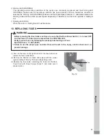
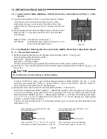
9 - 2 Control Panel Details
⑳
⑲
㉑
⑪
⑮
⑭
⑯
⑰
⑱
⑬
⑫
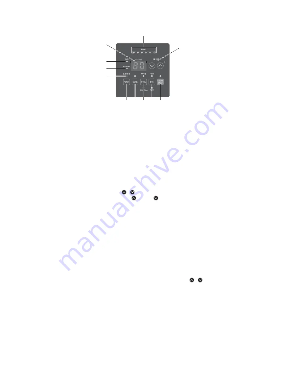
Fig. 13
⑪
Digital Speed Indicator
Preset Speed, Actual Speed, Warning and Error Codes are displayed in
2
digit format. When the motor is
stopped the Preset Speed is displayed, when the motor is rotating the actual speed is displayed.
The display also displays the error codes when an error has occurred. If Gear Ratio is on, the gear ratio will
be displayed.
⑫
Load Monitor LED (LOAD)
The
motor
spindle load is displayed by
6
LED
'
s (
3
Green,
2
Yellow and
1
Red). Continuous operation is
possible with up to all
3
green LED
'
s lit. If one of the yellow LED
'
s is lit the motor spindle can only be run for
a short time. Please refer to P
80
"
17
. PROTECT FUNCTION
"
section of this manual for allowable duration
of high load operation. When any of the yellow or red LED
'
s are lit the Warning LED (WARNING) will blink,
if this condition is continued beyond the allowable interval the Error LED (ERROR) will light and the motor
spindle will be shut down.
⑬
Motor Speed Adjustment Button (SPEED
,
)
(Manual adjustable speed control is possible. (
(UP) or
(DOWN).) (
1
digit is
1
,
000
min
-
1
(rpm).)
Sets the Gear Ratio when in Gear Ratio Mode.
Speed is adjustable from
1
,
000
-
80
,
000
min
-
1
(rpm). Maximum motor speed depends on the type of motor.
⑭
START / STOP Button (START / STOP)
Starts and stops motor rotation.
⑮
Rotation Direction Button (DIR)
Right hand rotation (FWD.) and left hand rotation (REV.) are as viewed with the cutting tool facing the
operator. With the cutting tool facing the operator right hand rotation (FWD.) will be clockwise rotation.
⑯
Control Button (CTRL)
This button will change the control mode to either MANUAL or AUTO.
MANUAL Mode : Controlled by Control Panel
②
.
AUTO Mode : Controlled by Input / Output Connector A
③
from External Signal Source.
⑰
Gear Mode Select Button (GEAR)
Set Gear Mode to display the rotating speed at the cutting tool when using an angle spindle or speed
reducer. Select the gear ratio by Motor Speed Adjustment Button (SPEED
,
)
⑬
. When setting Gear
ratio mode, the gear ratio will be displayed in Digital Speed Indicator
⑪
.
⑱
Error Reset Button (RESET)
This switch resets the alarm or error and allows restarting of the motor spindle after an error has been
corrected. Some error codes will not allow the unit to be reset until after the Main Power Switch
⑨
has
been turned OFF.
⑲
Error LED (ERROR)
When
a
serious
problem
with
the system, alarms are detected this LED illuminates. The motor may shut
down and the Digital Speed Indicator
⑪
will displays an error code.


