64
13
. MOTOR CORD CONNECTION
CAUTION
Before connecting to the Motor Cord Plug, make sure the Main Power Switch
⑨
is turned OFF.
If the Main Power Switch
⑨
is turned ON while connecting the Motor Cord Plug, damage may
occur to the CONTROLLER.
(
1
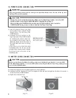
) Ensure the Alignment Pin is located upward (
12
o'clock position).
(
2
) Carefully insert the Alignment Pin into the Alignment Hole and push straight into the Motor Connector
⑥
on the front of the CONTROLLER.
(
3
) Tighten the Connector Nut.
Alignment Pin
Connector Nut
Alignment Hole
Fig. 23
Fig. 24
12
. POWER CORD CONNECTION
WARNING
Only use grounded power sources. Using a non-speci
¿
ed Power Cord, the risk of
¿
re by over-
heating of the cord is possible.
CAUTION
・
Reduce the risk of unintentional starting. Make sure the Main Power Switch
⑨
is in the OFF
position before connecting the CONTROLLER or plugging the system in.
・
When installing the CONTROLLER, provide space of approximately 10cm around the
CONTROLLER for easy access to the air inlet and the Power Cord Plug.
(
1
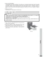
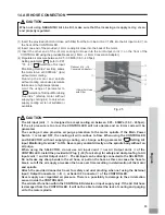
) Insert the female Power Cord Plug
into the Main Power Inlet with Power
Supply Fuses
⑩
on the front of the
CONTROLLER.
(
2
) A tapped hole is provided on the
lower, right side of the CONTROLLER
for attaching the tension relief. Use
the provided nylon tension relief to
attach the Power Cord to the side of
the CONTROLLER when mounting
vertically.
* When placing the CONTROLLER
horizontally (Fig.
19
), do not use the
provided nylon tension relief to attach
the Power Cord to the side of the
CONTROLLER.
Main Power Inlet with
Power Supply Fuses
⑩
Nylon Tension Relief
Fig. 22

