background image

65

English

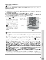
14. AIR HOSE CONNECTION

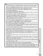
CAUTION

When not using NAKANISHI Air Line Kit, make sure that the incoming air supply is dry, clean 
and properly regulated.

(

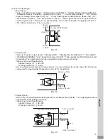
1

)  Insert the provided 

ȭ

6

mm Air Hose with Filter from the Air Line Kit AL - C

1204

 into the Air Input Joint 

 on 

the front of the CONTROLLER.

(

2

) Insert one end of the provided

ȭ

4

mm cooling Air Hose into the back of the motor.

(

3

)  Insert the other end of the

ȭ

4

mm cooling Air Hose into the Air Output Joint

 on the front of the 

CONTROLLER using the provided Reducer (

ȭ

6

mm - 

ȭ

4

mm Conversion Adaptor).

(

4

) Regulate air pressure between 

0

.

25

 - 

0

.

3

MPa (

36

.

3

 - 

43

.

5

psi).

Setting parameter

 (refer to P

91


"

18

 - 

4


Selection of Air Input 

Monitoring Override" section), allows 
the motor to run at 

30

,

000

min

-

1

 (rpm) 

without motor cooling.
Running the motor and spindle 
without cooling can cause premature 
failure due to high temperatures.
Limit the usage of parameter to 
"


Selection of Air Input Monitoring 

Override " (startup motor without 
supplying cooling air) to only when 
supply cooling air is not suitable or 
available.

Reducer (

ȭ

6 - 

ȭ

Conversion Adapter)

ȭ

6mm Air Hose 

with Filter

Fig. 25

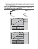
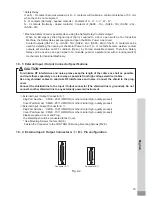
CAUTION

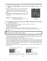
 The Air input joint 

, is designed to accept cooling air between 0.25 - 0.3MPa (36.3 - 43.5psi). 

If the air pressure is too low, the CONTROLLER will not operate and an Error code will be 
generated.

 The cooling air also provides air purge protection to the motor spindle. If the Main Power 
Switch 

 is turned OFF, the cooling air will continue to 

À

ow. When using the CONTROLLER 

and SELECTOR without supplying cooling air, change setting parameter 

"


Setting Air 

Input Monitoring Override " to ON. Never spray coolant directly on the spindle body without an 
air purge.

 When using the SELECTOR, do not use Air input Joint

 nor Air Output Joint

 of the 

CONTROLLER. Install the provided Air Plug (( 

 6) for air stop) for safety and dust proo

¿

ng to Air 

Input Joint 

 and Air Output Joint 

. The Air Input can be directly connected to the SELECTOR.

 Do not make any sharp bends in the air hose, or pull on the hose as this can cause the hose to 
break, cut off the air supply or weaken the hose over time resulting in deterioration of the motor 
and spindle.

 Attach the provided Connector Cover for safety and dust proo

¿

ng when not using the External 

Input / Output Connector A 

, B 

, or Serial I / F Connector 

 of the CONTROLLER.

 Never supply over regulated air pressure. There is a possibility to damage to the air detection 
sensor inside the CONTROLLER.

 The air detect function within the CONTROLLER detects air input supply only. If the Air Out hose 
is damaged from the CONTROLLER, it will not be able to detect the lack of cooling and purging 
air to the motor spindle.

Summary of Contents for E3000 SELECTOR

Page 1: ...OM K0438 005 取扱説明書 OPERATION MANUAL 日本語 P1 P44 English P47 P95 ...

Page 2: ...nt Operation Manuals carefully before use Always keep this Operation Manual in a place where a user can referred to for reference at any time CONTENTS IMPORTANT INSTRUCTIONS AND WARNING Electric Devices P48 1 CAUTIONS FOR HANDLING AND OPERATION P49 2 BASIC PACKAGE P52 3 WARRANTY P53 4 CONTACT US P53 5 FEATURES P53 6 SPECIFICATIONS AND DIMENSIONS P54 7 SYSTEM CHART P56 8 TORQUE CHARACTERISTICS P57 ...

Page 3: ...at has an outlet that looks like the one illustrated in Sketch A in gure See below 115V The tool has a grounding plug that looks like the plug illustrated in Sketch A in Figure below 8 FOR Installation in Machine Electrical Cabinet or when wiring directly to machine internal power terminal strip 1 Please refer to the pin diagram below for the proper wiring configuration The plug shown is the femal...

Page 4: ...ld work securely at all times 15 MAINTAIN TOOLS WITH CARE Keep tools sharp and clean for best performance and to reduce the risk of injury Follow instructions for changing accessories 16 DISCONNECT TOOLS before servicing or when changing accessories such as blades cutters etc 17 REDUCE THE RISK OR UNINTENTIONAL STARTING Make sure Main Power Switch is in OFF position before plugging in 18 NEVER LEA...

Page 5: ...ols as this may cause them to shatter or explode Tools with fractures or a bent shank will cause injury to the operator When using a new tool rotate it in a low speed and increase speed gradually for safety Do not exceed the maximum recommended allowable tool speed For your safety use speeds below the maximum allowable speed Do not apply excessive force This may cause tool slippage tool damage and...

Page 6: ...e spindle with less the regulated air pressure this may make you damage to the spindle or the CONTROLLER Be sure to clean the collet and collet nut the inside of the spindle before replacing the tool If ground particles or metal chips stick to the inside of spindle or the collet damage to the collet or spindle can occur due to the loss of precision Always clean the tool shank and the machine spind...

Page 7: ...n Body 1pc Power Cord 1pc ȭ6mm Air Hose with Filter 1pc Connector Cap 1pc Connector Cover A Connector Cover B Serial I F Connector Cover 1pc Each Nylon Tension Relief 1pc Bracket for bottom 1set Bracket for rear 1set Rubber Pad 4pcs 1set Fuse 2pcs Mounting Screw 9pcs Reducer ȭ6 ȭ4 Conversion Adapter 1pc Operation Manual 1set WARNING Error Code Label 1set The Connector Cap Connector Cover A B and S...

Page 8: ...layed This allows Error Codes to be reviewed if no one is present when the error occurs Error History will be stored to the CONTROLLER even if the Main Power Switch is turned OFF Since CONTROL will automatically recognize the motor attached and detect the maximum rotation speed there is no need to set maximum rotation speed based on types of motor 3 WARRANTY We provide a limited warranty for our p...

Page 9: ...the Motor Model Before using it check the speci cations of the motor and the motor spindle Since CONTROLLER will automatically recognize the motor types there is no need to adjust the maximum rotation speed based on the motor model FOR EM 3080J MOTOR AND HES810 SYSTEM USERS This motor spindle is designed to machine at min 1 rpm s between 20 000 and 80 000min 1 rpm only The 1 000 to 19 000min are f...

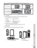
Page 10: ...nces by the European Union EU 6 3 Outside View Below is an outside view with Brackets Standard Accessory attached Fig 1 Bottom Mounting Fig 2 Rear Mounting 88 65 45 86 2 4 5 10 M4x0 7 Stepped Bracket 168 246 138 188 236 138 144 271 251 65 91 45 10 4 5 M4x0 7 Stepped Bracket Table 2 Identifying the Applicable CONTROLLER EM 3030T J EM 3030T J 2M Identifying Point Applicable CONTROLLER Non applicable...

Page 11: ...0min 1 rpm 32 000min 1 rpm 1 One piece Type Motor Cord EMCD 810 4M 6M 8M Brushless Motor Spindle HES510 Brushless Motor Spindle EMS 3060K Cord with Quick Disconnect Flange Type Brushless Motor Spindle EMSF 3060K Cord with Quick Disconnect CONTROLLER 100V 240V Air Line Kit AL C1204 Cooled air is supplied Motor Cord EMCD 3000J 3M 4M 6M 8M 60 000min 1 rpm Motor Cord Straight Type EMCD 3000 4M 6M 8M M...

Page 12: ...pm Brushless Motor EM 3030J EM 3030J 2M 1 000 32 000min 1 rpm Brushless Motor EM 3030T J EM 3030T J 2M 1 000 30 000min 1 rpm 60 000min 1 rpm 50 000min 1 rpm 50 000min 1 rpm Lever Type Spindle NRR 3060 60 000min 1 rpm Quick Change Spindle NRR3060 QC 60 000min 1 rpm Air Quick Change Spindle NRR3060 AQC SELECTOR 100V 240V Single motor can only be operated at the same time No simultaneous operation 60...

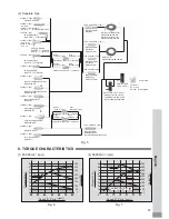
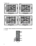
Page 13: ... 200 150 100 50 0 40 50 Torque cN m Output W Speed x103 min 1 rpm Fig 9 HES510 4 32 000min 1 rpm 10 20 30 32 0 8 9 7 6 5 4 3 2 1 200 150 100 50 0 250 300 350 400 450 Torque cN m Output W Torque Output Continuous Duty Area Continuous Duty Area Speed x103 min 1 rpm Fig 10 9 CONTROL PANEL FEATURES 9 1 System Fig 12 14 16 18 20 12 10 8 6 4 2 0 10 20 30 350 400 450 500 300 250 200 150 100 50 0 Torque O...

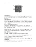
Page 14: ...nector Motor Connector Connect the Motor Cord Plug of the motor spindle Refer to P64 13 MOTOR CORD CONNECTION section Air Input Joint Supply clean dry regulated air for motor cooling Regulate air to between 0 25 0 3MPa 36 3 43 5 psi Max Air Consumption is 30Nℓ min Air must be supplied to operate the system at maximum rpm Refer to P65 14 AIR HOSE CONNECTION section Air Output Joint Connect Air Hose...

Page 15: ... Speed is adjustable from 1 000 80 000 min 1 rpm Maximum motor speed depends on the type of motor START STOP Button START STOP Starts and stops motor rotation Rotation Direction Button DIR Right hand rotation FWD and left hand rotation REV are as viewed with the cutting tool facing the operator With the cutting tool facing the operator right hand rotation FWD will be clockwise rotation Control But...

Page 16: ...he CONTROLLER Verify type and use only following the properly rated and type of fuse Speci ed fuses T1 6AL 250V Failure to use the proper type and rated fuse will result in re injury electric shock and or product damage Cap Fig 14 Warning LED WARNING The operating and working conditions of the system are constantly monitored and the Warning LED WARNING flashes when a hazardous condition has been d...

Page 17: ...tion of the Bracket 2 types of Mounting Brackets are provided for both Bottom mounting and Rear mounting The Bracket can be installed on the Bottom Mounting Fig 15 and Rear Mounting Fig 16 of the CONTROLLER 1 Attach the Installation Brackets 2pcs using the provided mounting screws 4pcs 2 Attach the CONTROLLER Bracket s Slotted Area to the machine using the provided mounting screws CAUTION If there...

Page 18: ...ounting Screws Rubber Pad Control Panel Mounting Screw Control Panel Fig 18 Fig 19 11 3 Proper Clearance CAUTION When installing 2 or more CONTROLLERs in the machine cabinet make sure to check that each unit has the proper clearance on all sides for suf cient air Àow Insuf cient clearance will cause heat damage to the CONTROLLER and SELECTORS When installing the CONTROLLER and SELECTOR refer to Fi...

Page 19: ...ble CAUTION Reduce the risk of unintentional starting Make sure the Main Power Switch is in the OFF position before connecting the CONTROLLER or plugging the system in When installing the CONTROLLER provide space of approximately 10cm around the CONTROLLER for easy access to the air inlet and the Power Cord Plug 1 Insert the female Power Cord Plug into the Main Power Inlet with Power Supply Fuses ...

Page 20: ...ssure is too low the CONTROLLER will not operate and an Error code will be generated The cooling air also provides air purge protection to the motor spindle If the Main Power Switch is turned OFF the cooling air will continue to Àow When using the CONTROLLER and SELECTOR without supplying cooling air change setting parameter Setting Air Input Monitoring Override to ON Never spray coolant directly ...

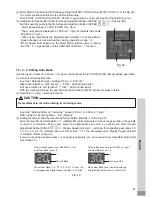
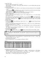
Page 21: ...utton SPEED of the Fig 26 To select 0 5 500 min 1 rpm push the Motor Speed Adjustment Button SPEED When controlling motor speed from 1 000 min 1 rpm to 500 min 1 rpm or from 500 min 1 rpm to 1 000 min 1 rpm stop the motor spindle prior to changing speed 3 Setting Gear Ratio Set the Gear Mode Select Button GEAR of the Fig 26 Push the Gear Mode Select Button GEAR GEAR LED will light Check the gear r...

Page 22: ...EV LED will illuminate With the cutting tool facing the operator right hand rotation FWD will be clockwise rotation 2 Set 500 min 1 rpm Centering Rotation Input the Rotates Motor at Centering speed Pin No 16 500 min 1 rpm When using the Centering Mode ON Closed 3 Setting Gear Ratio Set the Gear Mode Select Button GEAR of the Fig 28 Push the Gear Mode Select Button GEAR LED will be illuminated Chec...

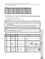
Page 23: ...xternal Speed Control Mode section Input the Count Pulse Signal for Setting Motor Speed Pin No 3 CNT_IN and UP DOWN Signal for Setting Motor Speed Pin No 15 UD_IN One pulse will increase or decrease 1 000min 1 rpm in Spindle Speed Counted on the leading edge of the signal UP DOWN Signal for Setting Motor Speed Pin No 15 UD_IN is ON Close increases speed OFF Open decreases speed Set by the Speed Po...

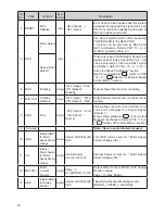
Page 24: ...No 22 If pin No 9 and No 22 are connected the CONTROLLER will be damage Pin No Code Function Input Output Description 1 COM_1 External Power source for External input Input DC0V or DC 24V Power source to be used for External Inputs Signals 2 DIR_IN Rotating Direction Setting Input OFF Open FWD ON Closed REV Controls the rotational direction of the motor spindle Setting parameter can start with rev...

Page 25: ...hows that the motor is rotating 7 DIR_OUT Rotating Direction Output OFF Open FWD ON Closed REV Output shows the direction of the Motor is rotating 8 ERR Error Output OFF Open Error ON Closed Normal Output shows that error has occurred Error code will be displayed on Digital Speed Indicator When setting parameter Error Output Mode can be changed Refer to P88 18 4 Setting of Error Output Mode sectio...

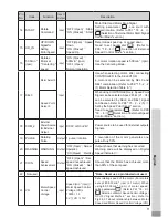
Page 26: ...1 signal combination Refer to P68 15 2 2 5 Set by the Speed Point Signal section Need to set parameter Refer to P90 18 4 Selection of External Speed Control Mode section 18 COM_2 External Power Source for External Output Input DC0V or DC 24V Power source to be used for External outputs Signals 19 PULSE Rotating Pulse Output 1 pulse rotation 1 revolution of the motor generates one pulse Duty 50 20 ...

Page 27: ...MG IN Signal set parameter Refer to P92 18 4 Selection of Emergency Stop Function sectional 2 When using the UD_IN and CNT_IN Signal set parameter Refer to P90 18 4 Selection of External Speed Control Mode section of the E3000 CONTROLLER Operation Manual Pin No Code Function Input Output Description 24 LOAD Torque Load Monitor Output Torque Load Monitor Torque Load Monitor Voltage x 20 Shows that ...

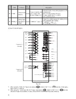
Page 28: ...ame DC 24V power source used for input signals Please refer to Fig 32 for connections Fig 31 Output Signal Ⅱ Refer to Fig 33 regarding the Output Signal of the Rotating Pulse PULSE The output signal can be connected for either sinking or sourcing Voltage and Current Speci cations Applied Voltage V DC 30V Working Current lp 50mA Fig 32 Fig 33 3 Input Output Signal Input Signal There are 8 different...

Page 29: ...7 5V 50 000min 1 rpm VR 㸼 DC 9 0V 60 000min 1 rpm VR 㸼 DC 4 8V 32 000min 1 rpm Max 30 000min 1 rpm VR 㸼 DC 4 5V 30 000min 1 rpm Torque Characteristics parameter is 32 000min 1 rpm 30 000min 1 rpm Fig 36 0 1 0 1 1 2 3 4 5 6 7 8 1 2 3 4 5 6 7 8 9 10 80 000min 1 rpm 60 000min 1 rpm 50 000min 1 rpm Motor Speed x10 000min 1 rpm Torque Characteristics parameter is VR DCV Max 80 000min 1 rpm Max 60 000mi...

Page 30: ...er Source input for Emergency Stop Signal or Emergency Stop Signal OFF Open External Power Source input for Emergency Stop Signal or Emergency Stop Signal Normal Operation ON Closed Emergency OFF Open When using the Emergency Stop Signal set parameter Refer to P92 18 4 Selection of Emergency Stop Function section 2 MT CNA Motor Connect Contact A Output Continuity OFF Open between Pin No 2 and Pin ...

Page 31: ...gnal Normal Operation ON Closed Emergency OFF Open When using the Emergency Stop Signal set parameter Refer to P92 18 4 Selection of Emergency Stop Function section 10 MT CNB Motor Connect Contact B Output Continuity OFF Open between Pin No 2 and Pin No 10 the motor is connected When there is continuity OFF between Pin No 2 and Pin 10 are OFF Open the selected motor is connected if no continuity t...

Page 32: ... Use an external power source for output circuits It is recommended to use a separate power supply Input Output Connector B Please refer to Fig 39 for connections Fig 39 DC 24V or DC0V DC 24V or DC0V DC0V or DC 24V DC0V or DC 24V or Load Load The side of CONTROLLER 2 MT CNA 10 MT CNB 5 AUTO 6 PWON 14 PWON 13 AUTO Pin No Code Function Input Output Description 14 PWON CONTROLLER Power Source Monitor...

Page 33: ...al is OFF Open the Safety Relay will be OFF Open and the motor power will be interrupted and the motor will stop If the NO Normally Open contacts of the Safety Relay are welded together by an over load or short circuit the NC Normally Closed contacts separation are maintained with more than 0 5mm spacing by the relay s recoil mechanism The voltage current speci cations of Pin No 3 11 and Pin No 4 ...

Page 34: ...switch of an Industrial Machine the Safety Relay will energize and open the Motor Power Line circuit Contact outputs SAFE 1A SAFE 1B SAFE 2A SAFE 2B of the N C contacts can be used for detecting the opening of the Motor Power Line If N O contacts become welded contact outputs will maintain an OFF condition Open by Forced Guide Mechanism Therefore Safety Relay can be used as an open signal of a mov...

Page 35: ...ir prior to use This will help prevent system errors that will result in non operational conditions 1 The WARNING LED WARNING will blink 2 The Warning Code listed in Table 7 will be displayed on the Digital Speed Indicator 3 A Warning Signal is output to the WARNING PIN No 20 WARNING of Input Output Connector A Table 7 Warning Code Warning Function Trouble A0 Motor Cord Motor Cord or Connector are...

Page 36: ...h is turned ON When Control Mode is AUTO the ERROR command is released without stopping the Control Command Signal OFF Open EL Incompatible Motor An unrecognizable motor is connected to the CONTROLLER EH Over Speed Rotating Speed is beyond the motors capability EE Emergency Stop Error Activated when Emergency Stop Signal is OFF Open or when rotating Emergency Stop occurred by Emergency Stop Signal...

Page 37: ...nge the Error Output Mode of the Error Signal for an Open or Closed state Refer to P88 18 4 Setting of Error Output Mode section CAUTION If you constantly operate the system in an overload condition even for short periods of time the CONTROLLER will overheat and damage to the CONTROLLER motor and spindle are possible NAKANISHI recommends only continuous duty operation LOAD LED s with 3 LED s lit T...

Page 38: ... Speed options can be selected when control mode is AUTO Analog Signal Pulse Signal Speed Point Signal Selection of External Motor Start Signal Control Mode When control mode is in AUTO please set the parameter to and set the desired rotating direction of the motor Activate Pin 2 to set a reverse direction along with the start command Selection of Air Input Monitoring Override If want to start the...

Page 39: ...ut Output Connector A When an error occurs the output can be select to ON Closed or OFF Open Signals can be output according to the required machine control logic of the system Table 10 Parameter Set Contents Error Occurred Signal is OFF Open Error Occurred Signal is ON Closed Table 12 Parameter Set Contents Fixed Motor Speed is enabled Fixed Motor Speed is not enabled Table 11 Parameter Set Conte...

Page 40: ...External Input Output Signal Motor Speed Control Voltage Pin No 23 VR When setting via the Pulse Signal use the External Input Output Signal Count Pulse Signal for Setting Motor Speed Pin No 3 CNT_IN and External Input Output Signal UP DOWN Signal for Setting Motor Speed Pin No 15 UD_IN The motor speed change per pulse is 1000min 1 rpm External Input Output Signal UP DOWN Signal for Setting Motor ...

Page 41: ...ir pressure is supplied Air pressure is not supplied Selection of Motor Speed Control Voltage DC 10V Signal Method Select the Motor Speed Control Voltage Signal and characteristics of the rotational speed according to the motor If parameter is set to the motor characteristics will be set to the motors maximum rotation speed 60 000min 1 rpm If parameter is set to the characteristics will be set to ...

Page 42: ...m Fig 44 0 1 0 1 1 2 3 4 5 6 7 8 1 2 3 4 5 6 7 8 9 10 80 000min 1 rpm 60 000min 1 rpm 50 000min 1 rpm Motor Speed x10 000min 1 rpm Torque Characteristics parameter is VR DCV Max 80 000min 1 rpm Max 60 000min 1 rpm Motor Type Description Max 50 000min 1 rpm Max 32 000min 1 rpm VR 㸼 DC 5 0V 50 000min 1 rpm VR 㸼 DC 8 0V 80 000min 1 rpm VR 㸼 DC 6 0V 60 000min 1 rpm VR 㸼 DC 3 2V 32 000min 1 rpm Max 30 ...

Page 43: ...ror code is displayed on the Digital Speed Indicator The Error History cannot be erased or deleted If Error History contains more than ve errors oldest Error History H5 will be deleted Con rmation of Parameter Setting This mode allows the user to check the settings of parameters The parameter can not be checked 18 4 Setting procedures Setting of Error Output Mode Procedure 1 Push the START STOP Bu...

Page 44: ...ation speed The Motor Rotation Speed range is 1 000 80 000min 1 rpm 6 Push the Error Reset Button RESET to send the settings to memory will be displayed 7 If you desire to set other parameters push the Motor Speed Adjustment Button SPEED to select the parameter that needs to be set 8 When you are nished setting parameters press the Error Reset Button RESET then turn the Main Power Switch is OFF Se...

Page 45: ...re and setting speed The Speed Point can be set Push the Motor Speed Adjustment Button SPEED to set the motor rotation speed Push the Error Reset Button RESET to send the settings to memory will be displayed If you are continuously setting these parameters push the START STOP Button START STOP 4 3 Alternately displayed are and the setting speed The Speed Point can be set Push the Motor Speed Adjus...

Page 46: ...P Button START STOP 4 is displayed This indicates that without supplying cooling air motor startup is possible with limited speed 5 You can cycle through the choices by pushing the START STOP Button START STOP 6 Push the Error Reset Button RESET while displayed on to store the setting 7 If you desire to set other parameters push the Motor Speed Adjustment Button SPEED to select the parameter that ...

Page 47: ... can cycle through the choices by pushing the Motor Speed Adjustment Button SPEED 12 Push the Error Reset Button RESET while is displayed 13 If you desire to set other parameters push the Motor Speed Adjustment Button SPEED to select the parameter that needs to be set 14 When you are nished setting parameters press the Error Reset Button RESET then turn the Main Power Switch is OFF Con rmation of ...

Page 48: ...pply Fuses of the CONTROLLER Check if a fuse is blown Motor Cord Plug is not connected to the Motor CONTROLLER or SELECTOR Connect the Motor Cord plug correctly to the Motor and CONTROLLER or SELECTOR Incompatible motor or motor spindle is connected to the CONTROLLER The Error Code EL is displayed on the Digital Speed Indicator Connect the connectable brushless motor or brushless motor spindle to ...

Page 49: ...tor Speed Control Voltage DC 10V Signal Method section Refer to P91 18 4 Selection of Motor Speed Control Voltage DC 10V Signal Method section Air Input Monitoring Override is set in the parameterto ON and the motor s maximum speed has been limited to 30 000 min 1 rpm Check the setting of parameter Refer to P91 18 4 Selection of Air Input Monitoring Override section A blinking dot appears on Digit...

Page 50: ...are worn Replace the collet and collet nut High run out The cutting tool is bent Change the cutting tool Collet nut is not correctly installed Secure the collet and the collet nut correctly The collet and the collet nut are worn Replace the collet and the collet nut Inside of the spindle is worn Replace the spindle shaft Return to NAKANISHI dealer service Contaminants inside the collet and the col...

Page 51: ...2017 01 27 03 ...

Reviews: