67
English
(
4
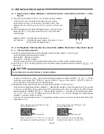
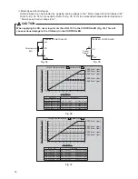
) Motor Start / Stop (Motor Start / Stop by pushing the START / STOP Button (START / STOP)
⑭
of the Fig.
28
.)
The motor spindle will start and the LED will illuminate.
Push START / STOP Button (START / STOP)
⑭
again and the motor will stop and the LED will go out.
(
5
) Setting Motor Speed (Set the Motor Speed Adjustment Button (SPEED
,
)
⑬
of the Fig.
28
.)
Set the speed by pushing the Motor Speed Adjustment Button (SPEED
,
)
⑬
.
・
Motor Speed Range is
1
,
000
-
80
,
000
min
-
1
(rpm).
・
The motor speed is displayed in
1
,
000
min
-
1
(rpm) increments.
80
equals
80
,
000
min
-
1
(rpm).
・
When using Gear Mode the Digital Speed Indicator
⑪
will show Motor
Speed changes at a slower rate than during operation at ratio
1
.
0
.
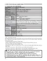
* Motor Speed limits depend on the Motor Model. Before using it, refer to
the P
54
"
6
-
1
Speci
¿
cation of the CONTROLLER Note :
1
" section.
⑭
⑰
⑬
⑪
15 - 2 - 2 Setting Auto Mode
Use the Input / Output Connector A
③
to input control signals to the CONTROLLER (Except setting gear ratio).
(
1
) Set motor Rotating Direction
Input the " Rotating Direction Setting (Pin No.
2
: DIR_IN) "
Right hand rotation is ' OFF (Open) ' ( " FWD ", LED will illuminate)
Left hand rotation is ' ON (Closed) ' ( " REV ", LED will illuminate)
With the cutting tool facing the operator right hand rotation (FWD.) will be clockwise rotation.
(
2
) Set
500
min
-
1
(rpm) Centering Rotation
Input the " Rotates Motor at " Centering " speed (Pin No.
16
:
500
min
-
1
(rpm)) ".
When using the Centering Mode : ' ON (Closed) '
(
3
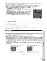
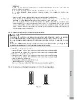
) Setting Gear Ratio (Set the Gear Mode Select Button (GEAR)
⑰
of the Fig.
28
.)
Push the Gear Mode Select Button
⑰
. (GEAR LED will be illuminated.) Check the gear ratio of the spindle
or reducer combination being used, select the appropriate gear ratio, by pushing the Motor Speed
Adjustment Button (SPEED
,
)
⑬
. Display Speed Indicator
⑪
, will show the
6
possible gear ratios:
1
.
0
,
1
.
5
,
2
.
7
,
4
.
0
,
6
.
0
,
16
. If GEAR ratio is set other than "
1
.
0
", the dot displayed on Display Speed Indicator
⑪
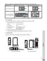
will blink. (Refer to Fig.
29
.)
If you are not using a speed reducer, or an angle type spindle, you do not need to set Gear Ratio Mode. (Set
Gear Ratio
1
.
0
)
When rotation speed is set 30,000min
-1
(rpm)
and Gear Ratio is set 1.5
⑪
Dot will Blink.
When rotation speed is set 30,000min
-1
(rpm)
and Gear Ratio is set 1.0
⑪
Dot turns OFF.
When Gear Ratio
“
1.5 / 2.7 / 4.0 / 6.0 / 16
”
is set, the
dot displayed on Digital Speed Indicator
⑪
will blink.
When Gear Ratio is set, the dot displayed
on Digital Speed Indicator
⑪
will turn OFF.
Fig. 29
Never attempt to cut while rotating in centering mode.
CAUTION
Fig. 28

