68
(
4
) Motor Start / Stop
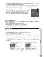
Input the " Rotate Command (Pin No.
14
: START) ".
Motor rotating is ' ON (Closed) '. When startup, RUN LED (RUN)
㉑
of the CONTROLLER will light and
motor will rotate.
(
5
) Setting the Motor Speed
・
Motor Speed Range is
1
,
000
-
80
,
000
min
-
1
(rpm). Maximum motor speed depends on motor and spindle
model.
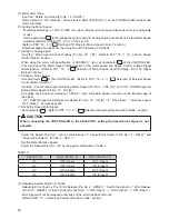
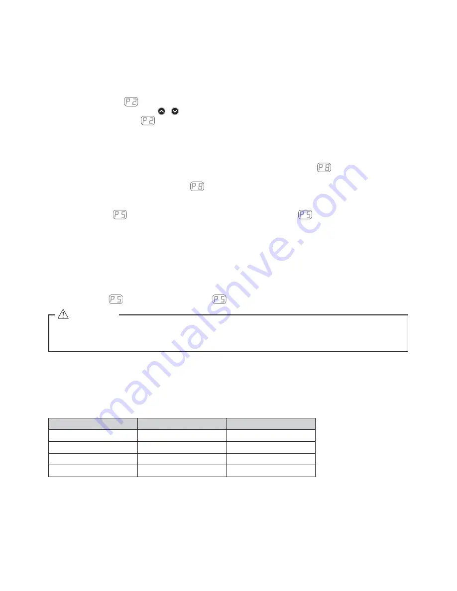
Setting parameter
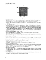
to ON allows the motor speed to be adjusted in Auto Mode using the Motor Speed
Adjustment Button (SPEED
,
)
⑬
of the Fig.
28
.
(Refer to P
89
"
18
-
4
②
Setting AUTO Mode for Motor Speed Control " section.)
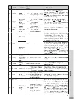
Rotational speed can be set by the using one of the following
3
methods.
①
Setting by Analog signal
Input the " Motor Speed Control Voltage (Pin No.
23
: VR) ". Refer to P
74
"
16
-
1
(
3
)
④
Motor Speed
Control Signal " section.
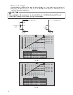
When using the motor with speci
¿
cation of
80
,
000
min
-
1
(rpm), set parameter
of the CONTROLLER.
This will change the Motor Speed Characteristics of the motor speed and Speed Control Voltage Signal
characteristics. (Refer to P
91
"
18
-
4
Selection of Motor Speed Control Voltage / DC+
10
V Signal
Method " section.)
②
Setting by Pulse Signal
(Set parameter
of the CONTROLLER. (Refer to P
90
"
18
-
4
⑤
Selection of External Speed
Control Mode " section.)
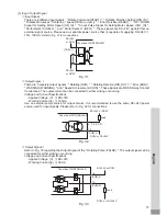
Input the " Count Pulse Signal for Setting Motor Speed (Pin No.
3
: CNT_IN) " and " UP / DOWN Signal for
Setting Motor Speed (Pin No.
15
: UD_IN) ".
One pulse will increase or decrease
1
,
000
min
-
1
(rpm) in Spindle Speed. Counted on the leading edge of
the signal.
" UP / DOWN Signal for Setting Motor Speed (Pin No.
15
: UD_IN) " is ' ON (Close) ' : increases speed,
' OFF (Open) ' : decreases speed.
③
Set by the Speed Point Signal
(Set parameter
. (Refer to P
85
"
18
-
3
⑤
Selection of External Speed Control Mode " section.)
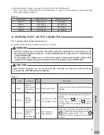
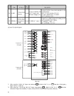
Select the Speed Point (U
1
- U
4
) by combination of " Speed Point Select
0
(Pin No.
17
: SEL
0
) " and
" Speed Point Select
1
(Pin No.
5
: SEL
1
) ".
Set the Motor Rotation Speed.
Select the Speed Point (U
1
- U
4
) by the signal combination in Table.
3
Table.
3
(
6
) Resetting System after Error Codes
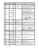
Releasing Error Code by The " Error Release (Pin No.
4
: RESET) ". Switch the signal on " Error Release
(Pin No.
4
: RESET) " of Input / Output Connector A
③
' OFF (Open) '
→
' ON (Closed) '
→
' OFF (Open) '.
Error Signal will not be released until cause of the error has been removed.
Refer to P
80
"
17
-
3
Resetting System after Error Code " section.
When connecting the CONTROLLER to the SELECTOR, setting the Speed Point Signal is not
possible.
CAUTION
Speed Point
SEL
1
(Pin No.
5
)
SEL
0
(Pin No.
17
)
U
1
OFF (Open)
OFF (Open)
U
2
OFF (Open)
ON (Closed)
U
3
ON (Closed)
OFF (Open)
U
4
ON (Closed)
ON (Closed)

