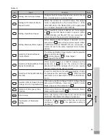
69
English
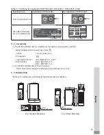
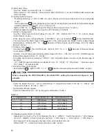
Select Motor
SEL1 (Pin No.5)
SEL0 (Pin No.17)
Motor 1
OFF (Open)
OFF (Open)
Motor 2
OFF (Open)
ON (Closed)
Motor 3
ON (Closed)
OFF (Open)
Motor 4
ON (Closed)
ON (Closed)
16
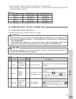
. EXTERNAL INPUT / OUTPUT CONNECTOR
16 - 1
External Input / Output Connector A
③
(
1
) Details of External Input / Output Connector A
③
Signals
WARNING
・
DO NOT connect any circuit other than SELV (DC+ 24V) (Safety Extra Low Voltage) to the
External Input / Output Connector A
③
of the CONTROLLER. This will cause I / O board damage
in the CONTROLLER.
・
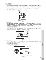
Do not supply over voltage or over current into the input / output circuit. Always install a LOAD
(resistor) to the output circuit to eliminate the chance of damage to the CONTROLLER.
Table.
5
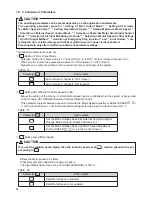
CAUTION
Input / Output Connector A
③
do not use Pins No. 9 and No. 22. If pin No. 9 and No. 22 are
connected, the CONTROLLER will be damage.
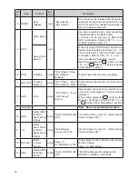
Pin
No.
Code
Function
Input /
Output
Description
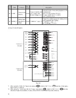
1
COM_
1
External
Power source
for External
input
Input
DC
0
V or DC+
24
V
Power source to be used for External Inputs
Signals.
2
DIR_IN
Rotating
Direction
Setting
Input
' OFF (Open) ' : FWD.
' ON (Closed) ' : REV.
Controls the rotational direction of the motor
spindle.
Setting parameter
, can start with reverse
rotation. (Refer to P91 " 18 - 4
⑥
Selection
of External Motor Start Signal Control Mode "
section.
)
3
CNT_IN
Count Pulse
Signal for
Setting
Motor Speed
Input
' OFF (Open) '
→
' ON (Closed) '
One pulse will increase or decrease
1
,
000
min
-
1
(rpm) in Spindle Speed depending on parameter
setting. (Refer to P
90
"
18
-
4
⑤
Selection of External Speed Control Mode"
section.)
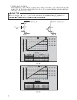
(7) Set Motor Selection (When connecting the SELECTOR to the CONTROLLER.)
After connecting a CONTROLLER to a SELECTOR,
4
motors can be selected by SEL
0
and SEL
1
combination. (Refer to Table.
4
.)
Table.
4

