72
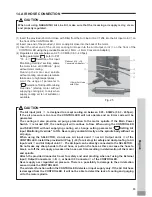
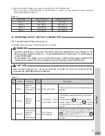
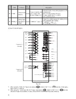
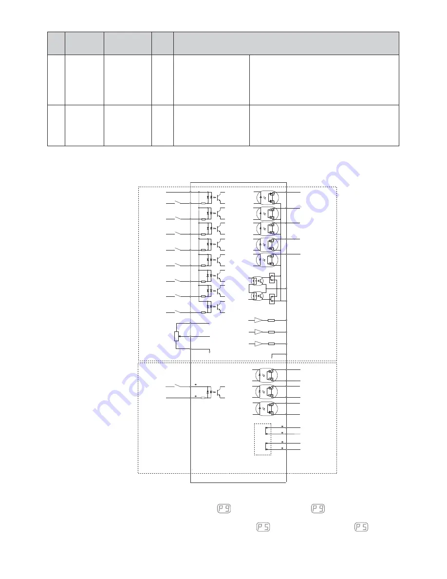
START
COM_1
(DC+24V or DC0V)
DIR_IN
RESET
500min
-1
(rpm)
SEL0
SEL1
UD_IN
*2
CNT_IN
*2
Potentionmeter
5K
Ω
COM_2
(
DC0V or DC+24V
)
RUN
DIR_OUT
ERR
WARNING
COIN
PULSE
MT-CNA
MT-CNB
AUTO+
AUTO-
PWON+
SAFETY RELAY CONTACT
PWON-
EMG-INA
*1
EMG-INB
*1
VR
+10VDC
GND
GND
MOTOR_1
LOAD
SPEED_V
SAFE-1A
SAFE-1B
SAFE-2A
SAFE-2B
1
14
2
4
16
17
5
15
3
11
23
10
1
9
6
7
8
20
21
19
18
12
24
25
13
2
10
5
13
6
14
3
11
4
12
Connector A
③
(D-Sub25)
Connector B
④
(D-Sub15)
(
2
) Input / Output Diagram
Fig.
30
*
1
When using the " EMG - IN " Signal, set parameter
. (Refer to P
92
"
18
-
4
⑨
Selection of Emergency
Stop Function " sectional.)
*
2
When using the " UD_IN and CNT_IN " Signal, set parameter
. (Refer to P
90
"
18
-
4
⑤
Selection
of External Speed Control Mode " section of the E
3000
CONTROLLER Operation Manual.)
Pin
No.
Code
Function
Input /
Output
Description
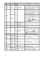
24
LOAD
Torque Load
Monitor
Output
Torque Load Monitor
(%) = Torque Load
Monitor Voltage x
20
Shows that the torque being applied to the
analog motor.
20
% / V
100
% (rating) / DC+
5
V
Torque Load Monitor :
0
-
200
%
(
0
V
≦
LOAD
≦
10
V)
25
SPEED_V
Rotating Speed
Analog Monitor
Voltage
Output
10
,
000
min
-
1
(rpm) / V
Output the rotation speed of rotating motor
with Analog Monitor Voltage.
10
,
000
min
-
1
(rpm) / V
0
V
≦
SPEED_V
≦
10
V

