75
English
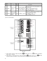
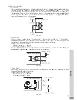
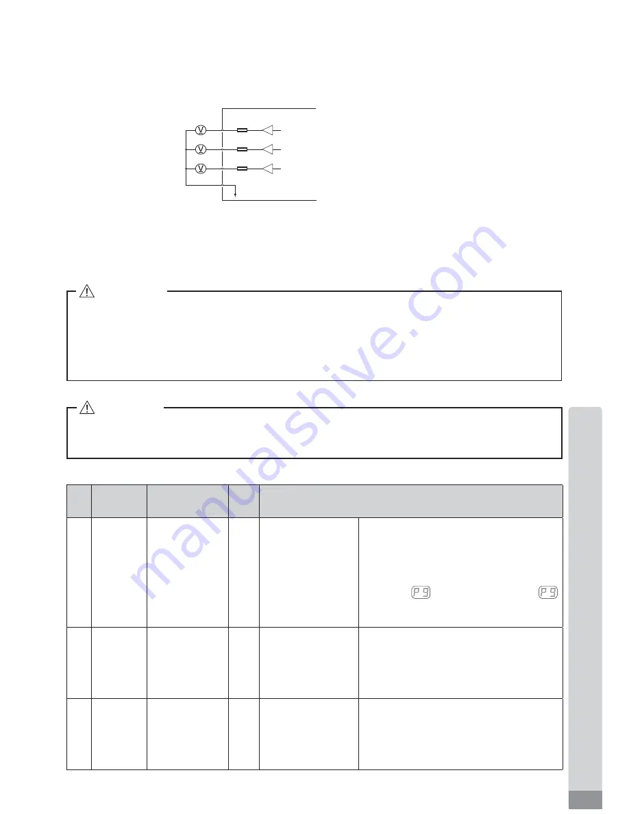
Fig. 38
The side of CONTROLLER
1K
Ω
1K
Ω
1K
Ω
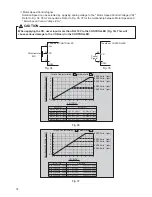
Motor Current Monitor
(
MOTOR_I
)
Torque Load Monitor
(
LOAD
)
Rotating Speed Analog
Monitor Voltage
(
SPEED_V
)
DC0V
12
24
25
13
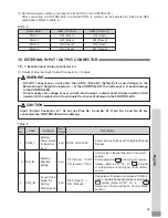
16 - 2 External Input / Output Connector B
④
(
1
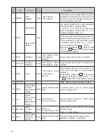
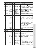
) Details of External Input / Output Connector B
④
Signals
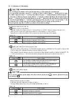
WARNING
・
DO NOT connect any circuit other than SELV ( DC+24V) (Safety Extra Low Voltage) to the
External Input / Output Connector B
④
of the CONTROLLER. This will cause I / O board damage
in the CONTROLLER.
・
Do not supply over voltage or over current into the input / output circuit. Always install a LOAD
(resistor) to the output circuit to eliminate the chance of damage to the CONTROLLER.
Table.
6
CAUTION
Input / Output Connector B
④
DOES NOT use Pin No. 7, No. 8, and No. 15. If pin No. 7, No. 8, and
No. 15 are connected, the CONTROLLER will be damage.
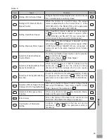
Pin
No.
Code
Function
Input /
Output
Description
1
EMG-INA
Emergency
Stop A
Input
External Power
Source input
for Emergency
Stop Signal or
Emergency Stop
Signal ' OFF (Open) '
External Power Source input for Emergency
Stop Signal or Emergency Stop Signal.
N o r m a l O p e r a t i o n ' O N ( C l o s e d ) ' ,
Emergency ' OFF (Open) '.
When using the Emergency Stop Signal, set
parameter
. (Refer to P
92
"
18
-
4
Selection of Emergency Stop Function "
section.)
2
MT-CNA
Motor Connect
Contact A
Output
Continuity, ' OFF
(Open) ', between
Pin No.
2
and Pin
No.
10
the motor is
connected.
When there is continuity, OFF, between
Pin No.
2
and Pin No.
10
and the selected
motor is connected, if no continuity is
present, the motor is disconnected or the
motor cord is broken.
3
SAFE-
1
A
Safety Relay
Contact
1
A
Output
Pin No.
3
and Pin
No.
11
continuity
' ON (Closed) '
Safety Relay is OFF
When there is continuity between Pin
No.
3
and Pin No.
1
are ' ON (Closed) '
Safety Relay is OFF (System Stopped), no
continuity Safety Relay is ' OFF (Open) '
Normal Operation.
⑤
Analog Monitor Signals
There are
3
types of monitoring signals :
"
Motor Current Monitor (MOTOR_I)
"
,
"
Torque Load Monitor
(LOAD)
"
, and
"
Rotating Speed Analog Monitor Voltage (SPEED_V)
"
. Please refer to Fig.
38
for
connections.

