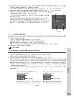
77
English
(
2
) Input / Output Signals
①
Output Signal
Pin No.
2
-
10
,
5
-
13
,
6
-
14
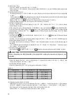
There are 3 different output signals : " Motor Connect Contact (MT-CN) ", " Control Mode AUTO Signal
(AUTO) ", and " CONTROLLER Power Source Monitor (PWON) ".
These signals are MOSS Relay Contact Connections. The output current can be connected for either sinking
or sourcing.
Voltage and Current Speci
¿
cations
・
Applied Voltage (V)
≦
DC+
30
V
・
Working Current (Ip)
≦
100
mA
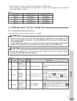
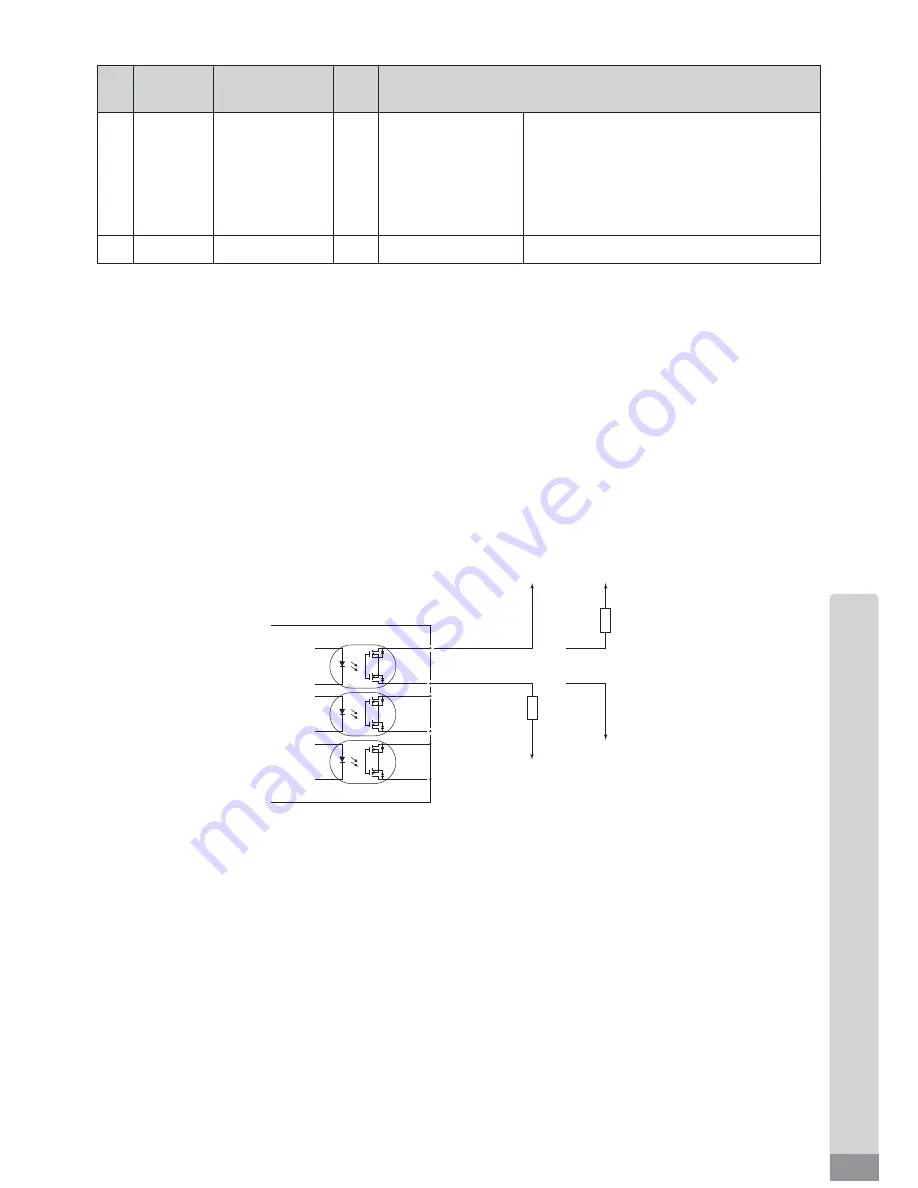
Use an external power source for output circuits. It is recommended to use a separate power supply
Input / Output Connector B
④
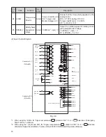
. Please refer to Fig.
39
for connections.
Fig. 39
DC+24V
or DC0V
DC+24V
or DC0V
DC0V or
DC+24V
DC0V or
DC+24V
or
Load
Load
The side of CONTROLLER 2 (MT-CNA)
10 (MT-CNB)
5 (AUTO+)
6 (PWON+)
14 (PWON-)
13 (AUTO-)
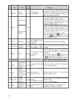
Pin
No.
Code
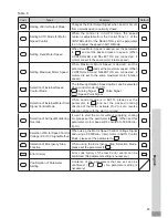
Function
Input /
Output
Description
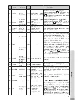
14
PWON -
CONTROLLER
Power Source
Monitor (-)
Output
' ON (Closed) ' :
Main Power Supply
is connected ' OFF
(Open) ' : Main
Power Supply is
disconnected
If the Main Power Switch
⑨
is ON, Pin No.
6
and Pin No.
14
are ' ON (Closed) '.
15
Not Used
―
―
―
*Note : Never use pin labeled not used.

