background image

NDSR660A

Thank you for your purchase and welcome to the world of Nakamichi! Please keep your
original proof of purchase or invoice in a sate place in case of any warranty claims. Do
also mail or register your warranty With the ofcial Nakamichi service centers and/or
agents to ensure that you are provided with the relevant technical support if required.

1. To prevent short circuit, please keep the device away from water or damp places. 
2. If water or any other liquid enters the device, cut off the power immediately, and inform 
    the nearest Nakamichi Service Center or Agent to inspect the product. 
3. Users are not recommended to disassemble the device as there are no user serviceable 
    parts inside, please contact the nearest Nakamichi Service Center if necessary.

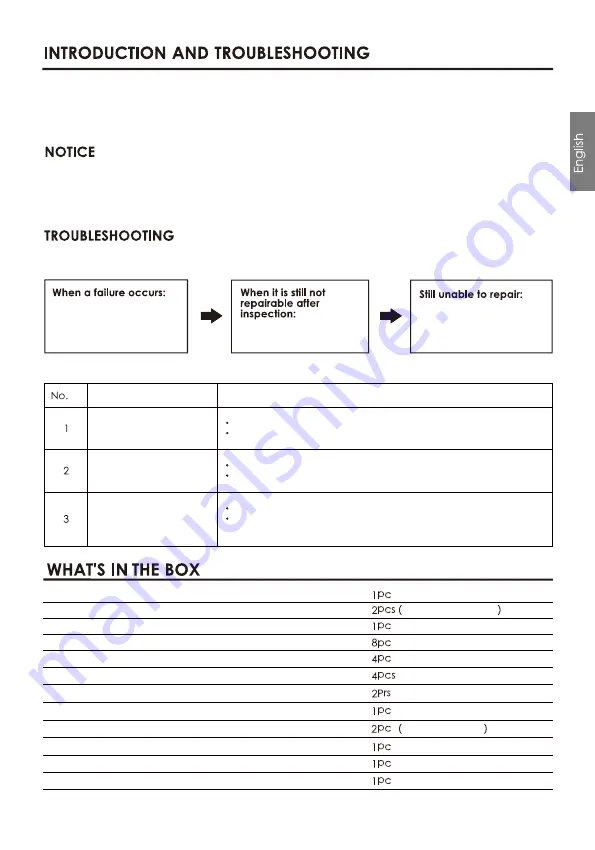
Ensure all cables and parts are securely connected before turning on the power.Shown
below is the basic troubleshooting procedure that you should follow.

Before sending the unit
for repair, please refer to
the table for common
troubleshooting solutions.

Please return the unit to
factory settings

Please consult the
nearest service center or
authorized agent for
further aptions

Troubleshooting method:

Malfunction

Reason and Solution

No Power

Check the power connection and make sure it's secure.
Check the ACC connection and make sure it's secure.

Double check if the unit is in MUTE mode.
Check if you have choose the correct input channel.

Check the USB connection and make sure it's secure.
Check if the driver " HID-compliant device " has been
properly installed in your PC.

Unable to connect
through USB

No Sound

USB2.0 Cable(1.5m)

Mechanical at head screws(PM3x6mm)

User Manual

Self-Tapping Oval Head Screws(PA4x20mm)

Mounting brackets

Velcro(160x20mm)

2 EN

8P high level input signal line(18cm)

16p Speaker cable(18cm)/8p Speaker cable(18cm)

6p power cable(18cm)

1Chinese,1English

35A FUSE

1Pc 16p,1Pc 8p

24P high level input and speaker cable(18cm)

Summary of Contents for NDSR660A

Page 1: ...NDSR660A ...

Page 2: ...1 EN ...

Page 3: ...ow is the basic troubleshooting procedure that you should follow Before sending the unit for repair please refer to the table for common troubleshooting solutions Please return the unit to factory settings Please consult the nearest service center or authorized agent for further aptions Troubleshooting method Malfunction Reason and Solution No Power Check the power connection and make sure it s se...

Page 4: ...r Output Phase and Time Alignment Presets 10 CH High Level 2 CH Low Level Built in Bluetooth U disk music Optical Coaxial 16 Channels low Level 16CHx25W Power Gain Range Mute 59 9dB 6dB 31 Band Equalizer Engine 1 Frequency range 20Hz 40KHz 1Hz Accuracy 2 Q value slope 0 404 28 852 3 Gain 20 0dB 20 0dB 0 1dB Accuracy Each output is equipped with multi order high and low pass independent lters 1 Fil...

Page 5: ... SP7 SP8 SP5 SP6 SP7 SP8 SPK OUT SP9 SP 1 0 SP11SP 1 2 SP 1 3 SP 1 4 SP 1 5 SP 1 6 SP9 SP 1 0 SP11SP 1 2 SP 1 3 SP 1 4 SP 1 5 SP 1 6 SPK OUT PWR PRO HOST ACC OPT COAX AUX IN R L REM USB PC H 1 0 H9 H8 H7 H 1 0 H9 H8 H7 HI LEVEL INPUT H6 H5 H4 H3 H2 H1 H6 H5 H4 H3 H2 H1 SP4 ACC SP3SP2 SP1 SP4 SP3SP2 SP1 REM OUT HI LEVEL INPUT SPK OUT GND GND GND 1 2V 1 2V 1 2V POWER ...

Page 6: ...C SP3SP2 SP1 SP4 SP3SP2 SP1 REM OUT HI LEVEL INPUT SPK OUT GND GND GND 1 2V 1 2V 1 2V POWER 4x25W 4 4x25W 4 OUTPUT CH9 CH7 CH5 CH8 CH6 CH2 CH4 CH3 CH1 CH10 CH11 CH13 CH15 CH12 CH14 CH16 SP5 SP6 SP7 SP8 SP5 SP6 SP7 SP8 SPK OUT SP9 SP 1 0 SP11SP 1 2 SP 1 3 SP 1 4 SP 1 5 SP 1 6 SP9 SP 1 0 SP11SP 1 2 SP 1 3 SP 1 4 SP 1 5 SP 1 6 SPK OUT 8x25W 4 ...

Page 7: ...P 1 0 SP11SP 1 2 SP 1 3 SP 1 4 SP 1 5 SP 1 6 SPK OUT 2 4 5 6 7 8 9 10 11 12 13 14 USB port Insert the USB ash drive and play the song in the USB ash drive under the player audio source USB2 0 Port Connect to the computer tuning software No need to download the driver installation connected to the computer sound software installed automatically Low level input port Connect up to 2 channels low leve...

Page 8: ...igh level input port High level output port 1 6 High level input 1 4 power amplifier output Machine start mode switch When the switch is turned to the ACC terminal the machine is started by ACC and when it is turned to the HOST terminal the machine is started by the high level H1 H1 input signal Power indicator light Protection indicator light Power port GND GND GND 1 2V 1 2V 1 2V POWER SP5 SP6 SP...

Page 9: ...1 Menu editing area Main functions File options operation a Click the File pop up window and select to load the scene on you computer save it as scene on you computer load the whole machine scene or save the whole machine scene b Click on Option to select Chinese and English switching Noise Gate RESET InPutVOL default source Input Attenuation ratio and About A 8 EN Note If you need to share tuning...

Page 10: ...X and USB Click the auxiliary audio source drop down list to select the input audio source AUX BT HI Level OPT COAX USB and OFF c Reset Click Reset to clear the channel type or restore the default channel type d Link Click the Link to set the Link synchronization mode copy from left to right or copy from right to left e Click Mixer to enter the mixing interface the interface is as shown below f Cl...

Page 11: ...d size or enter a value or roll the mouse wheel in the volume input box to adjust the sound size Click the speaker button to switch mute b Positive phase adjustment Click 0 or 180 to switch between positive phase and reverse phase c Delay set the delay value by scrolling the mouse wheel in the delay input box or enter the value to set the delay value d Delay Unit button Click the drop down list to...

Page 12: ...rs and the pass through mode the gain of all equalization points is restored to 0 dB the frequency and value are unchanged c Click PEQ Mode to switch GEQ Mode The Q value and frequency cannot be adjusted in the PEQ Mode interface 8 Channel EQ editing area Main function con guration Equilibrium design of current output channel 31 band equalization adjustable frequency Q value response bandwidth and...

Page 13: ...cal USB to choose from Auxiliary source AUX Bluetooth Hi level OPT Optical USB OFF to choose from Press and hold the volume scale clockwise or counterclockwise to adjust the volume The main volume range is 0 66 The subwoofer range is 0 60 The medium high D Volume adjustment and low volume range is 12dB 12dB E Scene preset There are 1 6 presets to choose from F Advanced settings Click Advanced Sett...

Page 14: ... mode and bridge mode Click link the joint debugging window will pop up and select the joint debugging method Corresponding to the adjustment of the output channel EQ curve gain Q value and frequency reset equalization pass through equalization or parametric equalization operation settings M EQ display Edit the display area N Output EQ gain Q value and frequency settings Output EQ gain setting A t...

Page 15: ...me recovery O Reset equalization restore equalization pass through equalization settings equalization Press the button and click Resume Equilibrium all values frequency Q value and gain will be restored to the value before the pass through Click P EQ Mode click OK to switch to Graphic Equalization click G EQ Mode click OK to switch to Parametric Equalization Six sound source modes can be selected ...

Page 16: ......

Reviews: