background image

7

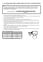
The proper surface speed for general grindstones is 10 - 30m / s.

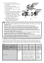
Do not exceed 13mm of overhang for mounted grindstones as shown in Fig. 12. If the overhang must exceed 
13mm, reduce the motor speed in accordance with Table 2.

Dress the grindstone prior to use.

Do not use cutting tools with bent or broken shanks, cracks or excessive run-out.

For grinding, the maximum depth of cut should not exceed 0.01mm radially or axially. Reciprocate the tool 
several times after each pass to eliminate tool pressure.

Always operate cutting tools within the allowable recommended speed of the cutting tools. Use of a cutting 
tool outside of the allowable speed of the cutting tools could cause damage to the spindle and injury to the 
operator.

Keep the cutting tool shank and collet chuck clean. If contaminants are left in the collet chuck or chuck nut, 
excessive run-out will cause damage to the cutting tool and or Spindle.

Do not strike or disassemble the Spindle.

Please minimize the tool overhang amount to maintaining high accuracy. 13mm is the maximum amount of 
overhang to maintain high accuracy and safety.

3.14 x Diameter (mm) x rotation speed (min

-1

) (rpm)

1,000 x 60

Surface Speed (m /s) 

=


9

. CAUTIONS WHEN USING GRINDSTONES AND TOOLS

CAUTION

The maximum surface speed or rpm is always specified for a grindstone. Do not exceed the 
maximum speed with reference to the calculating chart below. Always follow the grindstone 
manufacturer's recommendations.

Fig. 12

13

Table 

2. Overhang and Speed

Overhang (mm)

Max. Speed (min

-1

) (rpm)

20

N x 0.5

25

N x 0.3

50

N x 0.1

N = Max. Operating Speed with 

13mm overhang.

Summary of Contents for RA-151E

Page 1: ...glasses dust mask and use a protective cover around the Spindle whenever the Spindle is rotating Never connect disconnect or touch the Power Cord Plug or Motor Cord Plug with wet hands This may cause an electric shock Never operate or handle the motor and Spindle until you have thoroughly read the Operation Manuals and safe operation has been confirmed 1 To prevent injuries damages check the motor ...

Page 2: ...Do not exceed the capabilities of the Spindle or tools During supply of coolant spray do not stop the supply air pressure If stop the supply air pressure entering coolant spray to internal Air Turbine Spindle by lost air purge This may occur damage to the Air Turbine Spindle Carefully direct coolant spray to the tool Do not spray directly on the Spindle body Stop working immediately when abnormal ...

Page 3: ...he Spindle Align the thread on the front end of the motor and the rear of the Spindle and turn the Spindle clockwise If the drive shaft of the motor does not engage properly to the drive dog on the Spindle it may only turn aprroximately two threads before stopping DO NOT FORCE THEM TOGETHER Loosen the Spindle from the motor rotate the Spindle shaft by hand then re try The drive shaft and the drive...

Page 4: ...ndle is tight before using 4 Fig 3 8 5 Spindle Shaft 7 5 5 Loosen Tighten Wrench 5 5mm Tool Collet Chuck Wrench 8mm Set the provided 8mm wrench on the Spindle Place the provided 5 5mm wrench on the chuck and turn it counter clockwise to loosen the collet chuck and remove the tool Clean the collet chuck then insert the new tool and tighten the collet chuck by turning clockwise Do not overtighten Fi...

Page 5: ... Fig 9 CLAMPING AREA Grip Ring GR 30 Sold Separately Fig 6 When installing a Spindle use a Grip Ring GR 30 sold separately Fig 6 recommended If the Grip Ring GR 30 sold separately cannot be used due to the restriction of dimension and space install as shown in below Do not allow set screws to come directly in contact with the Spindle body as shown in Fig 9 as this will result in damage to the Spin...

Page 6: ...ype Holder so that the inside diameter of the Split Type Holder is ȭ30 with its tolerance range from 0 01mm to 0 015mm and its roundness and cylindricity of less than 5μm 7 When inserting the Spindle loosen the Fastening Bolt and twist the Screw for Removal and widen the Slit Area Front View Fastening Bolt Slit Side View Fastening Bolt Screw for Removal Spacer Fastening Bolt Spacer Screw for Remov...

Page 7: ...the spindle and injury to the operator Keep the cutting tool shank and collet chuck clean If contaminants are left in the collet chuck or chuck nut excessive run out will cause damage to the cutting tool and or Spindle Do not strike or disassemble the Spindle Please minimize the tool overhang amount to maintaining high accuracy 13mm is the maximum amount of overhang to maintain high accuracy and s...

Page 8: ...nd clean the collet chuck Reinstall the collet chuck The collet chuck is worn Replace the collet chuck High run out The tool is bent Change the tool Collet chuck is not correctly installed Secure the collet chuck correctly The collet chuck is worn Replace the collet chuck Inside of the Spindle is worn Replace the Spindle shaft Return to NAKANISHI dealer service Contaminants inside the collet chuck...

Reviews: