18
used and maintained.
Important. This equipment must not
be used for composting purposes
(shredding) as this could result in
injury or damage to property.
The machine is to be used only for its prescribed
purpose. Any other use is deemed to be a case
of misuse. The user / operator and not the
manufacturer will be liable for any damage or
injuries of any kind caused as a result of this.
Please note that our equipment has not been
designed for use in commercial, trade or
industrial applications. Our warranty will be
voided if the machine is used in commercial,
trade or industrial businesses or for equivalent
purposes.
5. Technical data
Mains voltage: 230-240 ~/50 Hz
Power: 350 W
Cutting circle: 25 cm
Revolutions n
0
: 12000 rpm
Cutting line diameter: 1.2 mm
L
pA
Sound pressure level measured 84,2 dB(A)
K
pA
uncertainty 3 dB
L
WA
Sound power level measured 94,72 dB(A)
K
WA
uncertainty 3 dB
Sound power level guaranteed: 96 dB(A)
Vibration emission value
main handle a
h
= 4,783 m/s
2
K uncertainty 1,5 m/s
2
Wear ear-muffs.
The impact of noise can cause damage to
hearing.
The declared value of the vibrations was
measured by a standard test method that can
be used for comparison tool with another. It can
also be used as part of a preliminary assessment
of the degree of exposure.
WARNING! The value of the actual vibrations
emitted while using the device may be different
from the declared value depending on how
the tool is used. Estimate the exposure in the
real conditions in order to identify the security
measures taken with regard to personal
protective equipment (taking into account all
parts of the business cycle: times when the tool
is off, when he is asleep, he is on).
The level of loudness perceived by the user may
exceed 85 dB(A), necessitating the use of ear
muffs.
6. Before starting the equipment
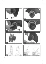
6.1 To put on the auxiliary handle (B3-B4):
Pull the ends of the auxiliary handle to extend
the handle and slide it over the handle holder.
(B3)
Screw down the screw (B4-1 and B4-2, Pos. 6) in
the auxiliary handle .
6.2 To adjust the auxiliary handle (B5):
The auxiliary handle can be set to various
positions. Adjust the handle such that the
cutting disk slightly tilts forward in your working
position.
Loosen the screw in the handle and move the
auxiliary handle (5) to your favourite position.
Tighten the
screw in the handle.
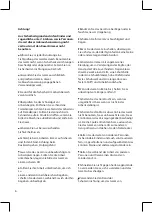
6.3 To put on the protective cover (B6-B7):
Place the protective cover (11) on the motor
head and screw it down with the screw (9).
6.4 To adjust the height (B8):
The telescopic shaft allows you to adjust the
appliance to your personal size.
Loosen the Lock for height adjustment (8).
Adjust the telescopic shaft to the correct length
Summary of Contents for 014508
Page 2: ...2 B1 B2 2 5 6 4 6 9 5 8 3 1 16 10 11 14 13 12 11 15...
Page 3: ...3 B3 B4 1 B4 2 B5 B6 B7 B8 B9 5 6 11 16 9 4 3...
Page 4: ...4 B12 B13 B11 B14 B15 B16 B17 7 15 B10 12...
Page 28: ...28 96dB 96dB A 16 1...
Page 29: ...29 GR On Off On Off 1 0mm2...
Page 30: ...30 On Off...
Page 31: ...31 5 a b 30mA a b c...
Page 34: ...34 12 10 B13 14 10 5 30 C 11 17 8 9 9 1 9 2 11 14...

