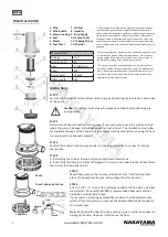
EN
WWW.NAKAYAMATOOLS.COM
2
STEP 7
A.
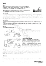
For most installations, install a full size 11/8’’ I.D thru-hull fitting to achieve the
rated flow of the pump. Located the thru-hull fitting at least 12’’ above the water line
to prevent water from flowing back into the hull when the pump is off.
B.
For stern installations, place the 11/8’’ thru-hull fitting high enough in the stern so
that submergence of the fitting will not occur under any conditions.
STEP 8 wiring
In order to prevent electrolysis and corroded wire connections, its essential that all wire ends and terminals be sealed with
heavy duty marine sealant and located above the highest possible water level by fastening with insulated staples or plastic
straps.
When installing your pump, 16 gauge wire should be used. However, if your installation is over 20” from the battery source,
the wire size should be increased to 14 gauge. Using a wire which is too small causes undesirable heat in the wires and results
in a voltage drop and lower performance of the pump.
STEP 9 fusing
To protect your electrical wiring and automatic switch from possible overload install a fuse in the positive (+) lead from the
battery.
If using a panel switch with a fuse holder, check to see that the proper fuse is being used. You may wish to install a panel
switch with a built-in fuse holder.
STEP 10
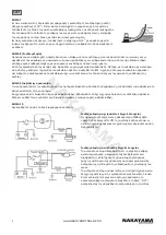
Follow one of the two wiring diagrams:
Storage
The pump itself is not affected by freezing temperatures. However, if the pump is embedded in ice or surrounded by ice, it
cannot be used. Never turn the pump on if it is embedded in or surrounded by ice.
Wiring for manual Operation
The manual system is the simplest system but it only pro
-
vides ON-OFF control of the pump. Consequently, pump are
often left ON longer than necessary.
Wiring for Automatic Operation
The automatic system assures that the vessel is always
pumped out, even when unattended. In extends the life of
the pump and your battery by automatically shutting the
pump off when the water has been pumped out.
The automatic system can also provide for manual control of
the pump by installing a panel switch. These switches have a
‘’fail-safe’’ feature which automatically returns the switch to
the ‘’ off’’ position , preventing the pump from being inad
-
vertently left on.
STEP 11
Polarity is important. If it is not correct, the pump rotate backwards. Water will still come out of the discharge nozzle but
the flow will be very much reduced. On the 1500/2000 pump the correct polarity will be obtained when the brown wire
of the pump is connected to the POS or +side of the battery. The way to verify that the direction of rotation (and thus the
polarity) is correct is to look into the running and see if the impeller rotates in the direction of the arrow placed into the
bottom. Never insert fingers or other objects into the inlet hole.
Summary of Contents for NP1160
Page 1: ...en gr WWW NAKAYAMATOOLS COM ART NO NP1160 024729...
Page 5: ...GR WWW NAKAYAMATOOLS COM 4 BHMA 7 A 11 8 I D 31cm 11 8 8 16 20 14 9 10 ON OFF OFF...
Page 6: ...GR WWW NAKAYAMATOOLS COM 5 BHMA 11 POS...
Page 7: ...DISPOSE OF PACKAGING RESPONSIBLY DO NOT DISPOSE OF ELECTRICAL GOODS IN HOUSEHOLD WASTE...


