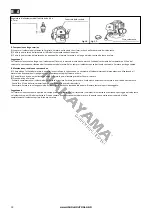
3. Wiring leads (Fig.3)
Connect the leads (x2) between the engine and gear case.
Make sure colours match and connections are securely tight.
4. Drill-to-gear case (Fig.4)
(1) Slide the clip band upward and pull the
pin out from its hole.
(2) Align the pin holes on the gear shaft
and drill shank, and insert the drill over the
shaft.
(3) Reinsert the pin through the pin holes
and lower the band until covering the hole.
Fig. 3
Leads
Fig. 4
Gear shaft
Pin
Drill shank
Clip band
Slide the clip band downwards
Slide the band upwards
Before usage
1. Checks
(1) Check parts are not loose nor missing. This goes ESPECIALLY for the spark plug.
(2) Check the air intake and outlet for clogging. This auger uses an air-cooled engine. If the air passage is blocked, the engine may overheat.
(3) Check
that
the air cleaner is not dirty. A dirty air cleaner will cause the auger to consume more fuel during work.
(4) Check the spark plug is not dead.
2. Replacing the grease in the gear case
Make sure to deliver the machine to the manufacturer’s authorized service department after every 100 operating hours in order to replace the grease in
the gear case.
Motor
1. Preparations before starting the motor
(1) Fill the tank with fuel. Use the mixture of gasoline composed of normal gasoline of automobile and our exclusive
o
il for two
-
stroke motor
s
.
Use a special type 2-
stroke
oil (30ml of oil for each 1L of unleaded gasoline 95 octane).
Precaution:
- If you use the fuel: with inadequate mixture
o
f proportion it will result in insufficient power or incorrect functions of motor.
- Dry all the remaining gasoline. It can stain your clothes or cause a fire.
(2) Cable regulator of accelerator (Fig.
6)
Adjust the loosening band of cable of the accelerator until it is between 1.0 and 2.0mm An excessive band will make the motor fail.
Fig. 6
Adjust the screw of the accelerator cable
Zipper nut
2. Start
(1) Move the ON/OFF switch away from the STOP position. The motor will not start if the ON/OFF switch is in the STOP position (Fig. 7).
(2) Press the
t
rigger
l
ever and move the lever of medium acceleration in the direction of the arrow (Fig.
7).
(3) Loosen the
t
rigger
l
ever; this will lock the lever of medium acceleration in position. Now you can start the motor (Fig.
7).
EN
WWW.NIKOLAOUTOOLS.GR
4
Summary of Contents for PD5230
Page 1: ...PD5230 WWW NIKOLAOUTOOLS GR ART NO 043256 2 2 FR RO el SL EN IT BG HR...
Page 24: ...4 12 1 2 ON OFF STOP ON OFF 12 5 13 13 6 14 15 EL WWW NIKOLAOUTOOLS GR 24...
Page 25: ...14 15 7 50 0 6 0 7mm 17 0 6 0 7mm 16 17 8 1 2 3 8 1 2 3 EL WWW NIKOLAOUTOOLS GR 25...
Page 27: ...BG 1 1 1 1 2 3 3 3 4 2 2 1 2 3 4 x3 x1 1 2 A WWW NIKOLAOUTOOLS GR 27...
Page 29: ...BG 11 4 8 5 9 6 7 3 11 1 2 4 12 1 2 STOP 7 8 9 10 WWW NIKOLAOUTOOLS GR 29...
Page 30: ...BG 14 15 5 13 6 14 15 7 50 0 6 0 7 17 12 13 WWW NIKOLAOUTOOLS GR 30...
Page 31: ...BG 8 1 2 3 8 1 2 3 16 17 0 6 0 7 WWW NIKOLAOUTOOLS GR 31...


