Assembly
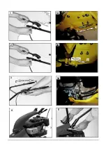
a).Assembly the Ex-arm-fixer(Fig.6) -
Place the Ex-arm-fixer on the gear box.
-Use the bolts1 to fix it.
b).Assembly the rock frame(Fig.7)
-insert the rock frame2 into the gear
box’s hole1.
c).Install the belt(Fig.8 )
-The belt1 cover the small belt wheel;
-Run the big belt wheel,then the belt cover
it. d).Fix the rock frame.(Fig.9)
-Use the spring1 and spring2 to fix rock
frame e).Assembly the cutting bar(Fig.10)
-Place the square-nut1 in the groove of
the cutting bar.
-Insert the bolt of the rock frame into
the square-nut1
-Connect the rock frame and cutting bar
using four bolts and locknuts2 .
f).Assembly the shield (Fig.11)
- Place the shield on the rocker frame;
- Use the nut1 and bolt2 to fix it.
Note:
The shake of this machine is bery big on
its
work,so every bolt or nut must be tighten
specially.
Adjustment
Note:
All the adjustments are started after off the
engine.
a).Cutting clutch distance adjust
-If the cutting clutch distance is too short,you
can adjust the cutting clutch line to L(Fig.1)
or L(Fig.2A) direction.
-If the distance is too long,you can adjust to
reverse direction.
b).Forward clutch distance adjust
-If the forward clutch distance is too short,you
can adjust the forward clutch line to L(Fig.1)
or L(Fig.1A) direction.
-If the distance is too long,you can adjust to
reverse direction.
d).Throttle line adjustd
-
When the throttle lever “o”,but the engine is
not off,you can adjust the throttle line to
R(Fig.1A) direction.
-
When the throttle lever don’t reach the “0”,
the engine is off,you can adjust the
throttle line to L(Fig.1A) direction.
e).Handbar height adjust.
To adjust the handbar height,loosen out the
height regulator select the appropriate hole,
reinsert and tighten it.
f).Cutting height adjust
The cutting height is adjusted using the
skids (Fig.12) .
Standard cutter bar
steplessly adjustable cutting height up to
approx. 6cm
• Loosen nut1 and. 2.
• Move the skids to the required height.
• Retighten the nuts.
Both skids must be set to the same height !
g).Cutting bar adjust to tighten.
After using a period,the upper blade and down
blade of the cutting bar become loosen,you
can take out the washer1(Fig.13).
Four positions must be set to the
same thickness!
Operation
1.Pre-operation check
a)Engine oil(Fig 4)
CAUTION:Running the engine the low
level cause serious eingine damage.
-Remove the oil filter cap3 and wipe
the dipstick clean;
-insert the kipstick into the oil filler neck,
but dot not screw it in;
-if the level is low,fill to the top of the oil
filler neck with the recommended oil.
Use high-detergent,permium quality 4-
stroke engine oil
Summary of Contents for SM8700
Page 1: ...Sm8700 Owner s manual Art Nr 013440 WWW NAKAYAMATOOLS COM...
Page 2: ...13 1 2 6 7 3 4 5 8 9 10 11 7 10 11...
Page 3: ...1 1A L 2 2A R L R 3 3A LL R 4 5 1 3...
Page 4: ...6 1 2 8 1 10 2 1 12 1 2 7 1 2 9 1 2 11 1 2 13 1...
Page 11: ...3 WWW NAKAYAMATOOLS COM GR 16 10...
Page 12: ...4 WWW NAKAYAMATOOLS COM Service 16...
Page 13: ...5 WWW NAKAYAMATOOLS COM 1 2 3 4 5 6 7 8 9 10 11 6 7 8 9 10 2 11 1 L 2 1 L 2 0 R 1A 0 L 1A 12...
Page 15: ...7 WWW NAKAYAMATOOLS COM O 20 6 80 3 50 6 7 8 0 7 0 8 mm 9 10 3 50 7 8 9 10 11 12...


