background image

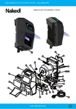
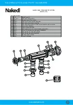
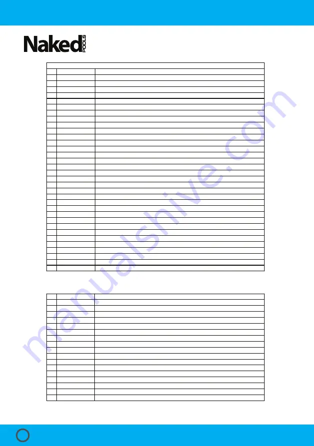
11. SCHEMATICS  AND  PART  NUMBERS

27

26

25

24

28

SL-15PP-NKD1

N00364

N00895

POWER PACK 

PARTS AND COMPONENTS (Not shown in schematic)

N00027

Thermostat 100degC

28

N00883

Ioniser Plug SL-13 Female End Complete with 2 x SL-09 Wire Looms


N00504

SM Cooling Fan 40x40x20mm (not in all models)

Power Cord-Au 

N00049

N00883

Thermostat 100degC

27

N00027

Cooling Fan 40x40x20mm (not in all models)

26

N00504

Power Cord-Au 

25

N00011

Internal Tooth Washer for Earth M5 S/S

24

N00049

Earth Nut M5 S/S

23

N00051

Earth Screw M5 S/S

22

N00050

NKD1 Snap Fit Gauze BLACK

21

N00370

20

N00369

NKD1 Bottom Vent Cover BLACK

19

N00368

Screw Pan Head M6x10 Stainless Steel 304 

18

N00503

Circuit Breaker 3amp with 6.3mm push on

17


N00018L

16

N00054

15

N00488

13


N00869

AC Socket Round - Pump Outlet Flush Mount White (Top Wire Entry)

12

N00498

Transformer 232VA for 15g/hr Model

8

N00496

7

Multi Triac Shunt PCB

6

NKD1 Decal Sticker (set of 2)

5

NKD1 Front Flap BLUE

4

NKD1 Vent Naked BLACK

3

NKD1 Cover BLACK

2

Wire Loom SL-12 - Multi PCB TB-GND Pin 1 to LCD PCB RB-GND Pin 1 BLACK

Naked DESCRIPTION

1

Naked NKD1 Power Pack  

  CODE

11

9

N00356

NKD1 Mounting Bracket

Grommet EC RP 6N-4 Cable Strain Relief Bush

Screw M3x12 Stainless Steel 304 (Fan)

NKD1 Fan Support Plate BLACK


Ioniser Plug SL-13 Female End Complete with 2 x SL-09 Wire Looms


N00693

N00870

N00367

N00842

N00022-1

N00011

NKD1 LCD Display PCB

Aluminium Die Casting with BLACK Outer Coating

10

N00453-2

Internal Tooth Washer for Earth M5 S/S

NKD1 Freshwater System Outer Box

46

N00079

45

N00873

Sleeve - NKD1 Freshwater System

44

N00876

NKD1 Power Supply Carton Box

43

N00067

42

N00052

Screw M4 x 8 Stainless Steel (Front Cover)

41

N00053

Screw Self Tapping M5x25 Stainless (Wall)

37

N00008

36

Wire Loom SL-11 - Ribbon Cable with RED line and Header Sockets

35

Wire Loom SL-05 - Terminal Block 1 Pin 2 to Terminal Block 2 Pin 2 RED

34

Wire Loom SL-04 - Circuit Breaker LINE to PCB A BROWN

33

Wire Loom SL-03 - AC Socket L to PCB PUMP-L BROWN

32

Wire Loom SL-02 - AC Socket N to PCB N BLUE

31

Wire Loom SL-01 - Circuit Breaker LOAD to Transformer Active BROWN

30

Washer 37x37x2.5 Zink Plated

   CODE

40

38

N00036

Green Wall Plugs

Screw M3x6 Stainless Steel (Triac Connection and PCB)

NKD1 Operating Manual

N00485

N00484

N00348

N00224

N00223

N00207

N00047

N00217

Wire Loom CC-05 - Earth Wire

Cable Tie 3mm

39

N00560

14

N00501

Grommet Rubber AUX Hole up to 19mm

Oxidiser Plug SL-10 Male End Complete with Power Supply Looms - Grease Filled

Naked Description

(PARTS LIST)

NAKED NKD1 FRESHWATER SYSTEM

www.naked-pools.com

30

Summary of Contents for NKD1

Page 1: ...Installation Operating Guide...

Page 2: ...8 4 2 Control Unit Installation 8 4 3 OXI Cell Housing Installation 9 4 4 ION Installation 9 5 STARTING YOUR NKD1 FRESH WATER SYSTEM 10 5 1 Switching on the Unit 10 5 2 Start Up Clock Set 10 5 3 Mine...

Page 3: ...ode 20 7 14 ION Setting 20 8 WATER CHEMISTRY 21 8 1 Copper 21 8 2 TDS Levels 22 8 3 pH 22 8 4 Total Alkalinity 22 8 5 Calcium Hardness 23 9 SYSTEM MAINTENANCE 24 9 1 Inspecting and Cleaning the OXI Ce...

Page 4: ...ding to AS NZS 3000 wiring rules It shall be installed outside the pool zone Please contact Naked Pools on 1300 625 331 for further assistance To reduce the risk of injury do not permit young children...

Page 5: ...f water Smart self cleaning technology allows the polarity of the OXI Cell plates to change direction every 4 16hrs depending on your setting Reversing times can be changed see 7 3 CELL CLEANING The c...

Page 6: ...HACKSAW NO 2 PHILIPS HEAD SCREWDRIVER PVC PRIMER AND GLUE A B 2X Green Wall Plugs with Screws The Installation Operating Manual 2X50 40 Redusing Bushes CONTROL UNIT OXIDISER IONISER HOUSING WITH UNIO...

Page 7: ...llow end of the pool and allowed to dissolve Do not let the salt settle on the oor of the pool as this may cause damage to the surface Use your pool brush to mix the salt into the water Running the pu...

Page 8: ...ot stored near chemicals fertilisers or in a closed unventilated shed with similar products as the fumes will cause excessive corrosion and damage to the internals of the Control Unit and may void war...

Page 9: ...gas trap that acts as a safety device Installation in any other way may cause explosion injury or death if the installer does not allow for gas removal A venturi pipe is installed moulded within the...

Page 10: ...al used in the pool Pressing or will change it from SALT to MINERAL MIX The reason for this is because a higher salt reading TDS value is required for MINERALS to be as conductive as SALT Pressing OK...

Page 11: ...y to ensure the copper levels are correct in the water based on the pool size entered in the previous screen 5 6 Default Display Screen DEFAULT DISPLAY SCREEN DDS displays the screen to the right This...

Page 12: ...N MENU allows you to enter all MENU s including those available with shortcut buttons on the control panel Pressing takes you to the last menu and using the or OK enters the rst 3 menus Pressing retur...

Page 13: ...ht Press OK to enter POWER MODE Pressing OK enters the display shown to the right and pressing the or allows you to adjust the POWER MODE setting from AUTO to OFF to ON Pressing OK saves the required...

Page 14: ...and decreases the time Pressing OK accepts the selected hour HH Pressing exits you to the DDS screen MM digits ash and pressing increases the time and decreases the time Pressing OK accepts the select...

Page 15: ...IME HH HH digits ash and pressing increases the time and decreases the time Pressing OK accepts the selected hour HH Pressing returns you to the previous display TIMER 1 OFF TIME MM MM digits ash and...

Page 16: ...i port valve to the backwash position ensure the handle locks in place and once ready press OK to enter the RINSE MODE cycle Pressing or BACKWASH allows you to exit and this takes you to BACKWASH COMP...

Page 17: ...tting by increments of 10 from 0 to 90 Once your desired set point is entered pressing OK will return to the DDS screen and the output will display at the lowered set point 50 or di erent if you set i...

Page 18: ...dge and keep the OXI plates clean Please note occasional cleaning of the plates may be necessary The factory setting is every 10 hours and this can be adjusted from as low as 4 hours for high calcium...

Page 19: ...lling to PUMP SETTING Menu 9 The default setting is 3 minutes and pressing or allows you to adjust the time the pump is turned o for Pressing OK saves the required protection time You can also select...

Page 20: ...3 seconds the direction will change to REV At the same time you will also be displayed the current reading in XXX Xamps Pressing returns you to the previous screen The TDS TEST measurement is meant to...

Page 21: ...not use Stabilizer Cyanuric Acid Do not use Bromine compounds Do not use Aluminium based or any other occulants Do not use Soda Ash Sodium Carbonate Do not use Granular Chlorine Do not use forms of Z...

Page 22: ...e your pool brush to mix the salt minerals into the water Running the pump will mix the water and help the salt minerals to dissolve 8 4 Total Alkalinity Measurement Interval Every 4 6 weeks 8 2 TDS L...

Page 23: ...er does not become too corrosive or end up scaling the surface of your pool These are symptoms of swimming pool water that is unbalanced THE MOST IMPORTANT NOTICE AND WARNING Only add chemicals in the...

Page 24: ...f your system All electrodes must be cleaned before scale calcium builds up to the point where the electrode gaps in the OXI Cell become bridged If the OXI Cell has excessive calcium deposit this may...

Page 25: ...eplace with new NKD ION Rods and repeat the process ensuring that the O ring is clean greased and properly seated and the Locking Ring is hand tight and secure Turn on the wall outlet switch and the p...

Page 26: ...Low water ow Water does not cover the water sensor Low speed pump not supplying su cient water to cell housing Increase the speed of the pump until housing is lled Build up of calcium on the Cell pla...

Page 27: ...does not work If the FAULT LED is ON then refer to above If only LCD DISPLAY is ON but nothing works call for service 1800 NAKED1 625 331 Sign of melting or burning of the OXI or ION Connector Plug P...

Page 28: ...ngs Make sure POWER MODE is set to AUTO Refer to Timer Setting in this manual sec 6 51 10 17 TDS level is to low Check TDS guide sec 7 10 8 2 pH is too high Check pH guide sec 8 3 Cell at the ends of...

Page 29: ...TICS AND PART NUMBERS NAKED NKD1 FRESHWATER SYSTEM 1 18 25 36 19 20 17 12 13 24 23 5 6 4 3 2 7 27 21 9 10 11 22 16 26 14 15 8 28 If in doubt please visit the website or call 1800 Naked1 www naked pool...

Page 30: ...Relief Bush Screw M3x12 Stainless Steel 304 Fan NKD1 Fan Support Plate BLACK Ioniser Plug SL 13 Female End Complete with 2 x SL 09 Wire Looms N00693 N00870 N00367 N00842 N00022 1 N00011 NKD1 LCD Displ...

Page 31: ...ble cover cap brassware washers resin lled 64 NKD1 Oxidiser Electrode Cap Locking Ring O Ring NKD1 Oxidiser Electrode EPDM rubber 63 62 Electrode Housing 3 Way Smokey Naked Description 61 NKD1 Oxidise...

Page 32: ...G SALT TEST YOUR POOL WATER FOR THE TOTAL TDS LEVELS RECOMMENDED TDS LEVELS FOR NAKED POOLS FRESH WATER SYSTEMS 800 1000PPM NEVER ADD SALT DIRECTLY TO THE SKIMMER BOX This high concentration of salt w...

Page 33: ...ability incurred by the manufacturer shall not in any case exceed the contract price for the equipment or the product parts or components thereof claimed to be defective Further the manufacturer shall...

Page 34: ...ld the guide be used as a substitute for such professionals No representations or warranities are made that the content advice and recommendations in this guide are current free from errors or omissio...

Page 35: ...15 NOTES If in doubt please visit the website or call 1800 Naked1 www naked pools com 35...

Page 36: ...swimming as nature intended P 1800 NAKED1 625 331 E warranty naked pools com W www naked pools com...

Reviews: