NAL Research Corporation (TN2014-001-V1.4.5)
10
The serial port allows a connected DTE to configure the 9602-LP using NAL Research’s defined AT
commands and any terminal emulator software. These AT commands can be found in the manual “AT
Commands for Model 9602-LP” TN2014-002-V1.4.5. Instead of trying to memorize various functions of AT
commands, NAL Research recommends the use of SatTerm graphical user interface (GUI) software to
configure the 9602-LP.
4.3 TTL/CMOS Inputs/Outputs
The 9602-LP has four TTL/CMOS inputs and three TTL/CMOS outputs. All I/Os are brought out to the
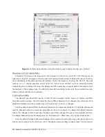
multi-interface connector. SatTerm should be used to configure these I/Os as shown in Figure 3 under the
I/O tab. The four CMOS/TTL inputs, denoted as S0 through S3, have internal pull ups which allow the inputs
to float as high. The inputs can be configured as emergency, test, or general input with a trigger on a rising
and/or falling edge. The trigger will activate the special functionality of the input type. Emergency configured
inputs will enable the Emergency Tracking mode when triggered. Test configured inputs will enable the Test
Tracking mode. General configured inputs will queue the transmission of an Input Report (see Appendix C
in “AT Commands for Model 9602-LP” TN2014-002-V1.4.5). Regardless of the type or trigger configuration,
the value of the input will be included in any version 5 GPS report sent. By default, S0 is configured as an
emergency input triggered by a falling edge and S1 is configured as a test input triggered by a falling edge.
S0 is shared with the on board emergency button. This means both the guarded emergency button on the
9602-LP and S0 can be used to activate Emergency Tracking.
Figure 3.
SatTerm Setup Window for I/Os.


