background image

NAL Research Corporation (TN2014-001-V1.4.5)  


        8 


Aided starts  1 second 


Warm starts   28 seconds 


Cold starts  

28 seconds 


Sensitivity: 

Tracking 

160 dBm 


Reacquisition 

160 dBm 


Cold starts 

147 dBm 

Operational Limits: 

COCOM restrictions apply 


Altitude 

164,000 feet (50,000 meters) 


Velocity 

1,640 feet/sec (500 m/sec) 


One of the limits may be exceeded but not both 


As long as power is provided to the 9602-LP, the GPS receiver will store ephemeris data in its memory 

before powering down (sleep between reports). The ephemeris data are valid up to two hours and can be 

used in future startup to improve time-to-first-fix. Unlike the 9601-DGS-LP, the 9602-LP does not need an 

extra back-up battery to retain ephemeris data. 


4.0 MULTI-INTERFACE CONNECTOR 


The multi-interface connector on model 9602-LP is a standard male 15-pin miniature D-Sub type (DB-

15). The connector comprises of four interfaces with the pin assignments shown in Table 1. These interfaces 
include: 


External DC power input 


3-wire RS232 serial data interface 


TTL/CMOS I/Os 


Reserved RS232 serial data interface 


PIN # 

SIGNAL 

DESCRIPTION 

INTERFACE 

EXT_PWR 

External power input (+3.6VDC to +5.3VDC) 

DC Power (+) 

EXT_GND 

External power input (GND) 

DC Power (GND) 

Tx1 

RS232 Input 

RS232 Data 

Rx1 

RS232 Output 

RS232 Data 

Signal_GND 

Signal Ground, 0V signal reference and return 

RS232 GND 

EMERGENCY


External TTL/CMOS Input S0 

0 – 5V TTL 

TTL 

TTL/CMOS Output 0 

0 – 5V TTL 

TTL 

TTL/CMOS Output 1 

0 – 5V TTL 

EXT_PWR 

External power input (+6.0VDC to +32.0VDC) 

DC Power (+) 

10 

Rx2 

Reserved 

RS232 Data 

11 

Tx2 

Reserved 

RS232 Data 

12 

TEST 

External TTL/CMOS Input S1 

0 – 5V TTL 

13 

TTL 

External TTL/CMOS Input S3 

0 – 5V TTL 

14 

TTL 

External TTL/CMOS Input S2 

0 – 5V TTL 

15 

TTL 

TTL/CMOS Output 2 

0 – 5V TTL 

Summary of Contents for 9602-LP

Page 1: ...F MODEL 9602 LP Version 1 4 5 May 30 2014 TN2014 001 V1 4 5 Copyright 2014 by NAL Research Corporation 9385 Discovery Boulevard Suite 300 Manassas Virginia 20109 USA Phone 703 392 1136 x203 E mail con...

Page 2: ...the performance or nonperformance of any products accessories facilities or services or information except as expressly stated in this guide and or the Product and or satellite service documentation...

Page 3: ...E DATA 7 4 0 MULTI INTERFACE CONNECTOR 8 5 0 CONFIGURATION SETTINGS 11 6 0 MOTION SENSOR 22 7 0 IRIDIUM ANTENNA CONNECTOR 23 8 0 GPS ANTENNA CONNECTOR 23 9 0 POWER CONSUMPTION 24 10 0 LIST OF KNOWN IS...

Page 4: ...raphical User Interface ID Static Identifier ISU Iridium Subscriber Units LED Light Emitting Diode LiIon Lithium Ion LNA Low Noise Amplifier LP Low Power NOC Network Operation Center OFAC Office of Fo...

Page 5: ...lso transmit in PECOS Message Structure PMS The PMS complies with the Blue Force Tracking Data Format Specification The 9602 LP supports 256 bit AES encryption algorithm NAL Research can enable the 96...

Page 6: ...or LiIon battery NOTE The DC power requirement was measured at the 9602 LP multi interface connector and not at the DC power supply Users must take into account voltage drop across the power supply ca...

Page 7: ...AC 47 60Hz input Car Adapter LA 7021 12VDC car battery input Power Cable HRC 24 12 HRC 24 12A 3 0 GPS RECEIVER PERFORMANCE DATA Type of GPS Receiver NEO 6Q from u blox AG Receiver Type L1 frequency C...

Page 8: ...ector on model 9602 LP is a standard male 15 pin miniature D Sub type DB 15 The connector comprises of four interfaces with the pin assignments shown in Table 1 These interfaces include External DC po...

Page 9: ...y voltage higher than 5 3VDC on pin 1 or accidently swap voltage between pins 1 and 9 The 9602 LP will be damaged beyond repair with warranty voided if this were to occur IMPORTANT User can remove the...

Page 10: ...ich allow the inputs to float as high The inputs can be configured as emergency test or general input with a trigger on a rising and or falling edge The trigger will activate the special functionality...

Page 11: ...ware to set up the 9602 LP instead of using AT commands When in Tracking mode the 9602 LP automatically transmits GPS reports defined by parameters in the active operating profile see description belo...

Page 12: ...nsor to transmit reports triggered by the Emergency switch or to transmit reports triggered by external devices The Callable No option is implemented when lowest power consumption is required because...

Page 13: ...rmal Tracking The Same Place Skip Reports option prevents GPS reports from being transmitted if the 9602 LP does not move outside a defined radius Under Callable Yes option the motion sensor signal is...

Page 14: ...etween reports of around 60 A at 5VDC The 9602 LP will not respond to any entered commands including the The command will work only while the tracker is waiting for GPS acquisition or is transmitting...

Page 15: ...ust exist before the 9602 LP sends a GPS report For example a car must experience continuous motion for three minutes before a GPS report is sent Otherwise a slight bump by a person or by a gust of wi...

Page 16: ...wer are shown in Figure 9 These parameters are very similar to the standard Callable No option except there is no Awake on Motion The 9602 LP uses Minutes of Motion Before Waking and Sensitivity to de...

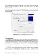
Page 17: ...can send GPS reports in AES 256 bit encrypted format Figure 10 displays SatTerm encryption setting window The GUI allows the Crypto Officer Password to be changed the encryption to be enabled or disa...

Page 18: ...is made from a command center while the 9602 LP is in the field The password entered must be 8 characters in length and all printable characters are allowed The factory set password is 12345678 and th...

Page 19: ...Ds provide the following information during Normal tracking mode Power LED lights up when power is applied to the 9602 LP and power on button is pressed GPS LED stays solid when there is a valid GPS p...

Page 20: ...em the LEDs display information in the same manner as during Normal tracking mode In addition the Status LED provides Status LED when first entering the Command mode this LED will not light up If the...

Page 21: ...9602 LP wakes up Start Up Mode sets the power up mode of the 9602 LP The 9602 LP allows GPS reports to be saved on its non volatile memory with Data Log Tracking option turned on When its memory is fu...

Page 22: ...eleration The sensor produces a series of TTL level logic or pulse train The signal level is fed directly into the 9602 LP s micro controller to wake up the 9602 LP out of sleep mode when activity is...

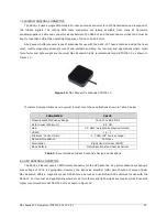
Page 23: ...esigned antenna is required it must meet the specifications shown in Table 2 below Table 2 Recommended Iridium Antenna s Design Specifications 8 0 GPS ANTENNA CONNECTOR The 9602 LP tracker uses an SMA...

Page 24: ...PS antenna other than the provided bias voltage will damage the 9602 LP 9 0 POWER CONSUMPTION This section gives users some insight to the electrical power profile of the 9602 LP It does not describe...

Page 25: ...in Figures 18 and 19 respectively 3 0 3 5 4 0 4 5 5 0 5 5 6 0 Voltage DC 0 00 0 04 0 08 0 12 0 16 0 20 Current A Figure 18 Average Current during Standby with 3 5VDC to 5VDC Input Voltage DC Current...

Page 26: ...ge range Figure 19 Average Current during Standby with 6VDC to 32VDC Input 5 10 15 20 25 30 35 Voltage DC 0 00 0 04 0 08 0 12 0 16 0 20 Current A Voltage DC Current A Figure 20 Average Power Consumpti...

Page 27: ...ng mode During the sleep segment the 9602 LP goes into power saving mode by shutting down all its internal circuits The average current drawn by the 9602 LP during sleep with 3 6VDC 5VDC input is show...

Page 28: ...from curve fitting cubic spline of the data Figure 23 shows the average power consumption by the 9602 LP during sleep for the entire voltage range 5 10 15 20 25 30 35 Voltage DC 0 60 120 180 240 300...

Page 29: ...The GPS acquisition time can range from 1 second hot starts to 28 seconds cold starts 3 0 3 5 4 0 4 5 5 0 5 5 6 0 Voltage DC 0 0 0 1 0 2 0 3 0 4 Current A Voltage DC Current A Figure 24 Average Curren...

Page 30: ...power consumption by the 9602 LP during GPS acquisition for the entire voltage range 0 5 10 15 20 25 30 35 Voltage DC 0 0 0 5 1 0 1 5 2 0 Power Consumption W Figure 26 Average Power Consumption during...

Page 31: ...6VDC 32VDC are shown in Figures 27 and 28 respectively 3 0 3 5 4 0 4 5 5 0 5 5 6 0 Voltage DC 0 0 0 1 0 2 0 3 0 4 Current A Figure 27 Average Current during SBD with 3VDC to 6VDC Input Voltage DC Curr...

Page 32: ...nnas poor visibility of the sky is when a clear line of sight is not available between the 9602 LP and the satellites 2 Keep the Iridium antenna s VSWR low the higher the antenna VSWR the higher the c...

Page 33: ...V1 4 5 33 11 0 TECHNICAL SUPPORT For technical support please contact us at Phone 703 392 1136 Ext 200 or E mail contact nalresearch com Technical documents are also available to download on NAL Rese...

Page 34: ...NAL Research Corporation TN2014 001 V1 4 5 34...

Page 35: ...e regulatory and technical certifications shown in table below Regulatory Approvals Radio Tests EMC Tests Mechanical Electrical Tests CE FCC Industry Canada ETSI EN 301 441 V1 1 1 2000 05 FCC CFR47 Pa...

Page 36: ...e laws and regulations Failure to comply can result in the imposition of fines and penalties the loss of export privileges and termination of your contractual agreements with NAL Research The export a...

Page 37: ...48 beams on the surface of earth which may be viewed as providing coverage cells on the ground similar to terrestrial systems Each beam is approximately 600 km in diameter The 66 satellite constellat...

Page 38: ...and operates an Iridium gateway located in Hawaii United States Each gateway generates and controls all user information pertaining to its registered users such as user identity geo location and bill...

Page 39: ...te LAN or an Internet service provider as shown in Figure D2 The handshaking and protocols are established between the modems independent of the landline The Iridium dial up data service functions in...

Page 40: ...gure B3 illustrates how Iridium Internet NIPRNet call is routed Direct Internet service can be enhanced using Windows based emulated point to point protocol PPP called the Apollo Emulator With the use...

Page 41: ...e 140 octet byte maximum message size SMS service is a store and forward method of transmitting messages to and from an Iridium modem The short message from the modem is stored in a central Short Mess...

Page 42: ...way The Iridium network can locate an ISU to within 10 km only about 78 of the time The so called error ellipse can have a large eccentricity with the major axis oriented in the azimuth dimension and...

Reviews: