521-OM0108.88
Copyright
2009 Nalco Company
5-12
Technical Help
(630) 305-CHEM
3D TRASAR
5500 - Installation & Operation Manual
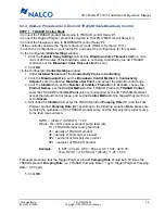
5.3.2 Start-up Procedure for 2-Drum 3D TRASAR Scale Tagged Polymer Control
(con’t)
STEP 3 - 3D TRASAR Scale Tagged Polymer Control Mode
• In the Configurator
Control Settings
window:
1. Click the
Inhibitor
tab, leave the
Tagged Polymer Control Method
in
Scale Index Control
.
2. Under
3D TRASAR Scale Control Settings
, click the
Setpoint Limits
button.
3. Enter
30%
for
Setpoint Increase Limit
,
0%
for
Setpoint Decrease Limit
, and click
OK
.
4. After returning to the
Inhibitor
page, uncheck the
Monitor Only (Setpoint does not
change)
box.
• Do NOT change any other settings.
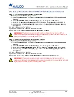
• Upload the modifications to the 3D TRASAR controller.
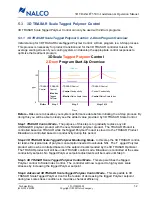
• The system is now under
3D TRASAR Scale Tagged Polymer Control
.
IMPORTANT
: The Tagged Polymer set point will now be increased by as much as 30% in
response to high system stress AND will be allowed to go below the user-entered set point
by as much as 10% in response to low system stress.
!
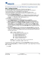
STEP 4 - Advanced 3D TRASAR Scale Tagged Polymer Control Mode
• In the Configurator
Control Settings
window:
1. Click the
Inhibitor
tab, leave the
Tagged Polymer Control Method
in
Scale Index Control
.
2. Under
3D TRASAR Scale Control Settings
, click the
Setpoint Limits
button.
3. Enter
30%
for
Setpoint Increase Limit
,
10%
for
Setpoint Decrease Limit
, and click
OK
.
4. After returning to the
Inhibitor
page, uncheck the
Monitor Only (Setpoint does not
change)
box.
• Do NOT change any other settings.
• Upload the modifications to the 3D TRASAR controller.
• The system is now under
Advanced 3D TRASAR Scale Tagged Polymer Control
mode.
IMPORTANT
: The Tagged Polymer set point will now be increased by as much as 30% in
response to high system stress but will NOT be allowed to go below the user-entered set
point since the “Set Point Decrease Limit” is 0%.
!

