521-OM0108.88
Copyright
2009 Nalco Company
6-8
Technical Help
(630) 305-CHEM
3D TRASAR
5500 - Installation & Operation Manual
6.4
3D TRASAR Bio-Control/3D TRASAR Bio-Shock Start-Up
Procedure (con’t)
• Any further question regarding the relay wiring and setup, please contact 3D TRASAR
Support or NGES Help Desk.
!
NOTE
: Verify oxidant residual is below 0.1 ppm TRH before proceeding any further! Use
DPD Total Colorimetric Test (
P/N 460-S0461.87
) with the Nalco DR/890 or DR/2800.
STEP 3
- Using the Configurator, set up the controller for 3D TRASAR Bio-Control or 3D TRASAR
Bio-Shock mode.
•
In the System Information window, enter the system volume (system volume needs to be
as accurate as possible).
•
In the Control Settings window, set the oxidizing biocide control method to “3D TRASAR
Bio-Control” or “3D TRASAR Bio-Shock Mode”.
•
If using scheduled Ox slugs with 3D TRASAR Bio-Control or 3D TRASAR Bio-Shock
mode, set up the slug parameters (prebleed, feed, post feed and recovery) in the Ox slug
window.
•
If using Ox slugs or 3D TRASAR Bio-Shock mode, make sure the ORP probe is clean and
calibrated.
•
Select the desired bio-reporter and indicate if the oxidant feed pump is optimally sized,
oversized or undersized for the system.
•
In the Alarm Settings window, select the appropriate Alarm Pump Duty for the oxidizing
biocide (see Section 4.5.4).
•
Upload the modified configuration to the controller.
•
Check to make sure the Configurator program asked for a ‘Reinitialization or Reboot’ of
the Controller. If not, either power cycle the Controller using the on/off switch or Reboot
from Configurator program.
STEP 4
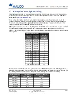
- If using a pellet feeder and the system volume exceeds 160,000 gal, deliver the required
number of bio-reporter Quick Dose Pouches to the cooling system (see Section 6.7).
6.5
Pellet Feeder Operation
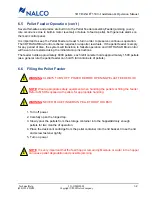
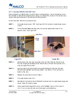
The 3D TRASAR Pellet Feeder automatically feeds pelletized bio-reporter to the cooling system at
predetermined intervals and dosages (# of pellets) as directed by the 3D TRASAR controller.
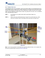
The feeder consists of a chemical hopper to hold the pelletized product, a motorized ball valve and
feeder neck assembly. This is connected to a piping assembly containing a y-strainer designed to
trap the fed pellets in a flowing water stream where they quickly dissolve into the circulating water.
When a pellet is to be fed, a signal from the controller initiates the process. The feeder assembly at
the bottom of the hopper, not unlike that in a “gumball” machine, rotates and traps a pellet, drops it
down into the feeder tube past an LED that ‘counts’the pellet, and into the ball valve assembly
which then rotates to drop the pellet into the flowing water stream.

