3D TRASAR
5500 - Installation & Operation Manual
521-OM0108.88
Copyright
2009 Nalco Company
2-18
Technical Help
(630) 305-CHEM
2.4 STEP 4 – Plumb Controller
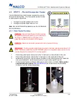
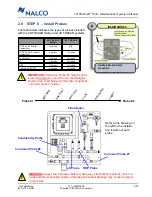
The 3D TRASAR system has one sample water inlet
plumbing connection and two sample water outlet
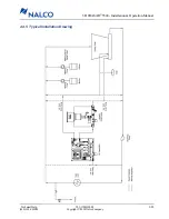
plumbing connections. Refer to the Typical Installation
Drawing in Section 2.4.5 for a general installation
overview.
2.4.1 Sample Point Selection
!
IMPORTANT
: Sample water flow must be a
minimum of 5 gpm.
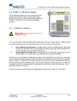
It is very important to select the appropriate sampling point for your cooling system. Sample points
are system dependent and should be taken from one of the following two locations:
1.
Recirculating Pump Discharge
- Sample points from the recirculating pump discharge
provide the maximum pressure opportunity for achieving the 5 gpm flow requirement of
the 3D TRASAR system and the Pellet Feeder.
2.
Return Header to Cooling Tower -
Sample points from the return header give the best
representation of corrosion rate measurements due to system heat loads.
In either case, it is important to understand the impact of the sample point in relation to control lag
times of the chemical feed (lag time is the time it takes the chemical to travel from point of injection
to the controller). In general, the shorter the lag time, the better the control (provided good mixing
has been achieved and recirculation rates are nominal). However, in cooling systems, the effects of
long lag times can be compensated for by decreasing the feed rate of the chemical pump, which
will reduce set-point overshoot.
Consult your Nalco representative for the appropriate sample point location for your system.
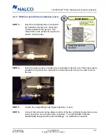
Plumb using ball valves provided. Inlet
water from recirculating system must be
at 5 GPM or greater.
Outlet
½”
Union
0.5
GPM
Plumb controller


