3D TRASAR
5500 - Installation & Operation Manual
521-OM0108.88
Copyright
2009 Nalco Company
2-26
Technical Help
(630) 305-CHEM
2.6.1 Fluorometer Installation
The fluorometer is shipped unattached to prevent damage.
Install as follows:
STEP 1
-
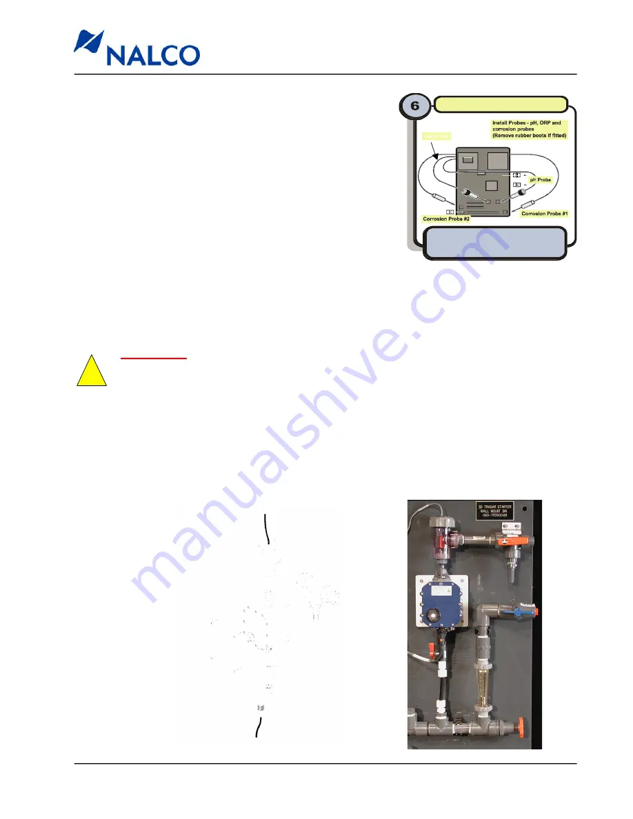
Locate and unpack the fluorometer,
fluorometer inlet valve, tubing connector, and
fluorometer outlet assembly (comprised of a
flow switch housing and three-way ball valve).
STEP 2
-
Attach the inlet valve and tubing connector to
the fluorometer inlet using teflon tape
(Do not over tighten).
STEP 3
-
Thread the fluorometer outlet assembly to
outlet of the fluorometer (do not overtighten).
STEP 4
-
Remove the end cap from the sample supply tubing. Connect the supply tubing to
the fluorometer inlet tubing connector.
STEP 5
-
Mount the fluorometer (and outlet assembly) to the back panel with the screws
provided. DO NOT FORCE!
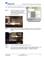
Install probes
Install probes and attach
connectors as shown.
Tighten swage fitting fully.
ORP Probe
Install probes
Install probes and attach
connectors.
IMPORTANT
: The length of the sample supply tubing may need to be adjusted to attain
proper alignment of the mounting screws with the back panel. DO NOT BEND sample
tubing. Excessive force may break fluorometer inlet fitting and internals. A broken inlet
fitting will necessitate the purchase of a new fluorometer which will not be covered under
warranty.
!
STEP 6
-
Connect the flow switch shuttle (pre-wired to the controller) to the flow switch hous-
ing. Adjust the position of the ball valve as needed to maintain proper alignment with
the flow switch assembly (slotted holes are provided on the three-way valve bracket
for adjustments.)
STEP 7
-
Connect the pre-installed fluorometer cable to the fluorometer.


