3D TRASAR
5500 - Installation & Operation Manual
521-OM0108.88
Copyright
2009 Nalco Company
2-32
Technical Help
(630) 305-CHEM
2.7 STEP 7 - Wiring
WARNING
: Always turn off power before
making any electrical connections, which
includes all interconnecting cables, other-
wise permanent damage may occur to
system components.
!
Wiring
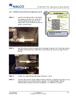
Connect cable between controller box and
pellet feeder. Wire pumps using supplied
pigtails (or hardwire). Connect 85 to 250
VAC @ 20 amps power using supplied
power cord (or hardwiring).
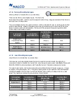
Electrical connections to the 3D TRASAR are either made
directly to the controller box or a junction box depending on
which model you have:
2.7.1 General Information
• All electrical connections must conform to applicable state and local codes.
• Supply power must be 85-250VAC @ 20 amps on separate GFCI protected circuit.
• A power cord without termination has been provided. A proper plug for 20-amp service
must be provided or the unit may be hard wired (using 12 AWG. wire).
• Failure to provide 20-amp service could result in intermittent operations, caused by circuit
breaker overload
• Probe connections are made through coaxial cables with waterproof connectors at the
probe.
• Pump connections can be made via supplied “pigtails” with receptacles, or hardwired (using
14 AWG. wire) directly to the terminals inside the control box as appropriate.
• There are 7 control relays individually fused at 2.5 amps (designed to operate at 2 amps).
In cases where more amperage is required, the control relays can be wired as dry contacts
for motor starters.
• Alarm outputs are fused at 1 amp.
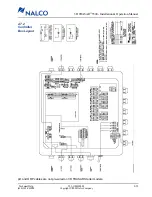
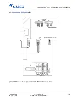
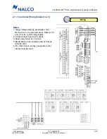
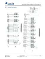
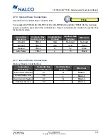
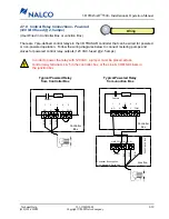
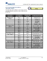
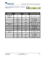
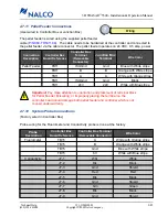
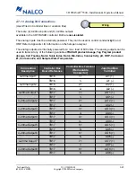
• Refer to the following diagrams and charts for details on wiring connections.
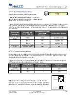
3D TRASAR electrical connections are made
directly in the controller for models
060-TR3500.88, 060-TR3501.88,
060-TR5500.88, and 060-TR5501.88
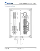
3D TRASAR electrical connections are made
in the junction box for all other models.
Junction Box

