3D TRASAR
5500 - Installation & Operation Manual
521-OM0108.88
Copyright
2009 Nalco Company
2-39
Technical Help
(630) 305-CHEM
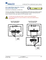
2.7.8 Control Relay Connections - Powered
(120 VAC fused @ 2.5 amps)
(User Wired in Controller Box or Junction Box)
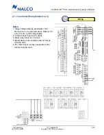
There are 7 pre-defined control relays in the 3D TRASAR controller that can be wired for powered
or non-powered operation. Follow the wiring diagrams below to connect metering pumps and
valves for powered control relay outputs (120 VAC, fused @ 2.5 amps).
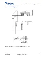
Typical Powered Relay
from Controller Box
Typical Powered Relay
from Junction Box
Wiring
NO
N
L
COM
1
2
3
4
5
Fuse
BLK
WHT
GRN
Controller
Box
Typical Powered Relay
Output from Controller Box
Contact
In order to power the relay with 120 VAC, a jumper must be placed across
control relay terminals 4 & 5 in the controller box, or the Line & COM terminals in
the junction box.
!
LINE
BLK
Jumper
COM NO
N
NO
N
L
COM
1
2
3
4
5
Fuse
Controller
Box
Earth Ground Bus
WHT
GRN
Junction
Box
Typical Powered Relay
Output from Junction Box
Controller Box supplies
Line, Neutral, & Earth Gnd
Contact

