3D TRASAR
5500 - Installation & Operation Manual
521-OM0108.88
Copyright
2009 Nalco Company
2-46
Technical Help
(630) 305-CHEM
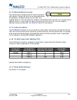
2.7.14 Factory Wired Digital Inputs
(Factory Wired in Controller Box or Junction Box)
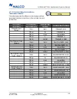
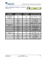
There are two factory wired digital inputs. The first is the
fluorometer flow switch, which is used to suspend control of any relay associated with the fluorom-
eter upon loss of sample flow.
The second digital input is the system interlock, which is intended for use on cooling systems that
operate intermittently. Afactory installed jumper wire is placed across the terminals of this input
(leave in place under normal operation). Removal of this jumper will suspend operation of ALL
control relays and initiate an alarm.
2.7.15 User Wired Digital Inputs
(User Wired in Controller Box or Junction Box)
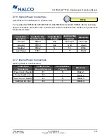
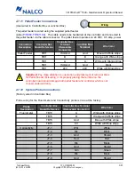
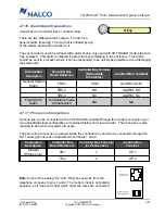
There are two user wired digital inputs that can be used to log and/or alarm the state of an
unpowered contact or totalize the counts from a low frequency pulse water meter.
Note
: Please call
630-305-CHEM for wiring assistance with “hall-effect sensor” transistor output water meters.
For water meter inputs, each pulse represents a pre-defined amount of water usage (i.e., 10 gal-
lons/pulse, 100 gallons/pulse, etc.). The gallon scaling factor is user-defined in the 3D TRASAR
Configurator.
Note
: The minimum on-time and off-time pulse width is 5 milliseconds for a valid
pulse. The maximum number of pulse counts is 10 per second.
Connection
Description
Controller Box
Board Reference
Controller Box Terminal
(Removable
Connector)
Junction Box
Terminal
Digital Input 3
TB10
3 (+)
DI3 (+)
TB10
3 (-)
DI3 (-)
Digital Input 4
TB10
4 (+)
DI4 (+)
TB10
4 (-)
DI4 (-)
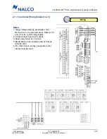
Wiring
Connection
Description
Controller Box
Board Reference
Controller Box
Terminal
(Removable
Connector)
Junction Box Terminal
Digital Input 1
Fluorometer Flow
Switch
TB10
Flow (+)
N/A
TB10
Flow (-)
N/A
Digital Input 2
System Interlock
TB10
INTERLOCK (+)
INT (+)
TB10
INTERLOCK (-)
INT (-)


